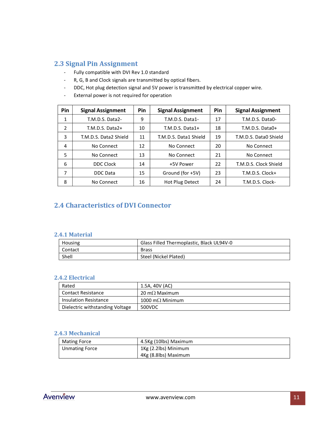
2.3Signal Pin Assignment
-Fully compatible with DVI Rev 1.0 standard
-R, G, B and Clock signals are transmitted by optical fibers.
-DDC, Hot plug detection signal and 5V power is transmitted by electrical copper wire.
-External power is not required for operation
Pin | Signal Assignment | Pin | Signal Assignment | Pin | Signal Assignment |
1 | T.M.D.S. Data2- | 9 | T.M.D.S. Data1- | 17 | T.M.D.S. Data0- |
|
|
|
|
|
|
2 | T.M.D.S. Data2+ | 10 | T.M.D.S. Data1+ | 18 | T.M.D.S. Data0+ |
|
|
|
|
|
|
3 | T.M.D.S. Data2 Shield | 11 | T.M.D.S. Data1 Shield | 19 | T.M.D.S. Data0 Shield |
|
|
|
|
|
|
4 | No Connect | 12 | No Connect | 20 | No Connect |
|
|
|
|
|
|
5 | No Connect | 13 | No Connect | 21 | No Connect |
|
|
|
|
|
|
6 | DDC Clock | 14 | +5V Power | 22 | T.M.D.S. Clock Shield |
|
|
|
|
|
|
7 | DDC Data | 15 | Ground (for +5V) | 23 | T.M.D.S. Clock+ |
|
|
|
|
|
|
8 | No Connect | 16 | Hot Plug Detect | 24 | T.M.D.S. Clock- |
2.4 Characteristics of DVI Connector
2.4.1 Material
Housing
Contact
Shell
Glass Filled Thermoplastic, Black
Brass
Steel (Nickel Plated)
2.4.2 Electrical
Rated | 1.5A, 40V (AC) |
Contact Resistance | 20 mΩ Maximum |
Insulation Resistance | 1000 mΩ Minimum |
Dielectric withstanding Voltage | 500VDC |
2.4.3 Mechanical
Mating Force | 4.5Kg (10lbs) Maximum |
Unmating Force | 1Kg (2.2lbs) Minimum |
| 4Kg (8.8lbs) Maximum |
www.avenview.com | 11 |
|
|
