4 | 290A Installation Instructions |
6.Now position the widget (10) inside the swivel (11) with the cables coming through the opening. Match the F and R on the widget with the F and R on the swivel, assuring that F remains at the front and R at the back.
7.Line up the positioning bolt (13) with the screw hole in the widget (10) and tighten it using the large allen key (1).
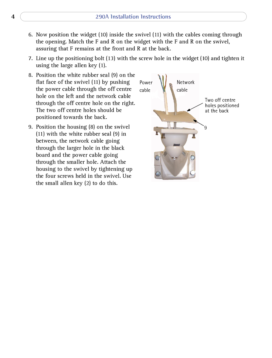
8.Position the white rubber seal (9) on the flat face of the swivel (11) by pushing the power cable through the off centre hole on the left and the network cable through the off centre hole on the right. The two off centre holes should be positioned towards the back.
9.Position the housing (8) on the swivel (11) with the white rubber seal (9) in between, the network cable going through the larger hole in the black board and the power cable going through the smaller hole. Attach the housing to the swivel by tightening up the four screws held in the swivel. Use the small allen key (2) to do this.
Power Network
cablecable
Two off centre holes positioned at the back
9
