290A Installation Instructions | 5 |
Connecting the camera
Warning: Be sure to work inside the housing in dry conditions. Rain water, moisture and prolonged con- densation inside the housing may cause serious damage to the camera and disturb the picture quality when in operation.
Warning: High voltage - the apparatus works on
1.Open the housing by releasing the two clips on the side.
2.Strip back the mains power cable by 5mm. The minimum mains cable conductor area for installation of the housing is 0.5 mm2.
Warning: Regulations relating to other parts of the system may require a bigger conductor area. You are responsible that the requirements of these regulations are met.
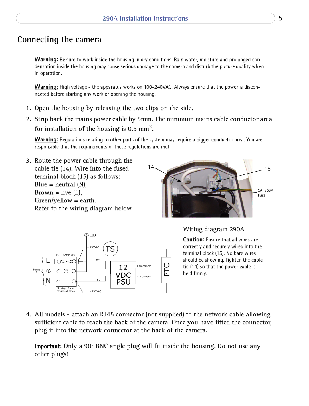
3. Route the power cable through the | 14 |
|
cable tie (14). Wire into the fused | 15 | |
terminal block (15) as follows: |
|
|
Blue = neutral (N), |
| 5A, 250V |
Brown = live (L), |
| |
| Fuse | |
Green/yellow = earth. |
|
|
Refer to the wiring diagram below.
Wiring diagram 290A
Caution: Ensure that all wires are correctly and securely wired into the terminal block (15). No bare wires should be showing. Tighten the cable tie (14) so that the power cable is held firmly.
4.All models - attach an RJ45 connector (not supplied) to the network cable allowing sufficient cable to reach the back of the camera. Once you have fitted the connector, plug it into the network connector at the back of the camera.
Important: Only a 90° BNC angle plug will fit inside the housing. Do not use any other plugs!