Manuals
/
Axis Communications
/
Photography
/
Security Camera
Axis Communications
Axis 216MFD-V, AXIS 216MFD, AXIS 216FD-V
manual
Unit connectors, Page
Models:
AXIS 216FD-V
1
14
74
74
Download
74 pages
38.15 Kb
11
12
13
14
15
16
17
18
Install
Connection diagram
Password
Indicatori LED
Dimension
Web in Configurazione
Recommandée pour
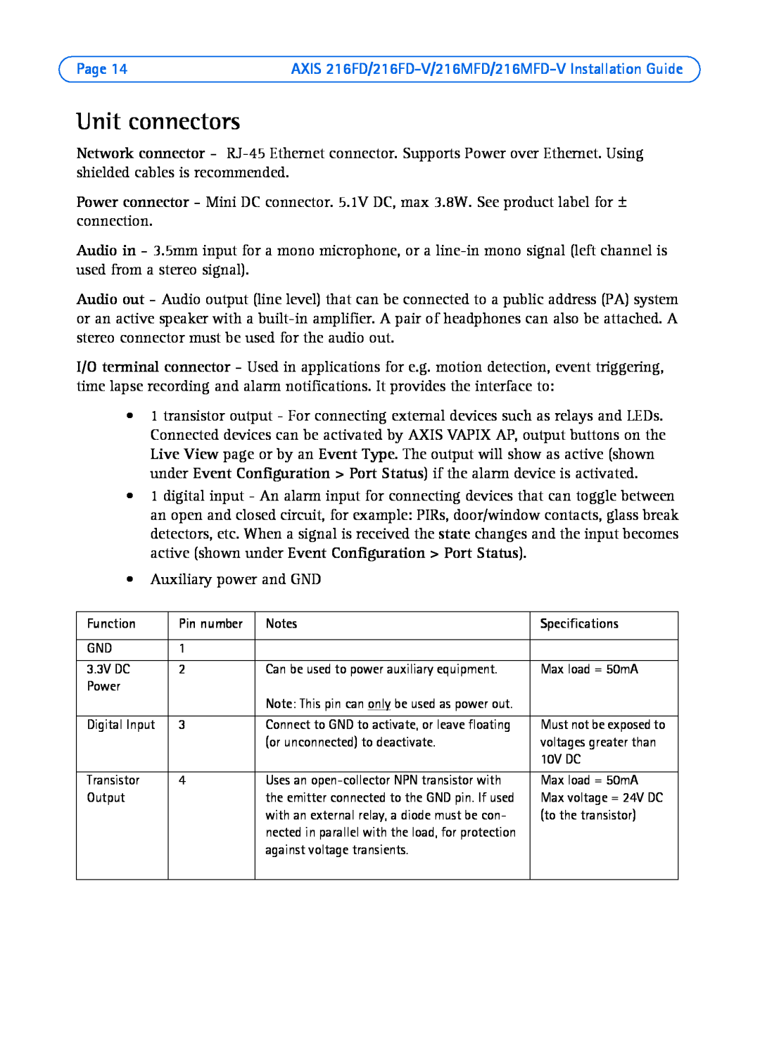
Unit connectors
Adjust the image and focus
Page 14
Image 14
Page 13
Page 15
Page 14
Image 14
Page 13
Page 15
Contents
ENGLISH FRANCAIS DEUTSCH ITALIANO ESPAÑOL
Fixed Dome Network Camera Installation Guide
AXIS 216FD AXIS 216FD-V AXIS 216MFD AXIS 216MFD-V
Page
Package contents
AXIS 216FD/216FD-V AXIS 216MFD/216MFD-V Installation Guide
Installation steps
AXIS 216FD/216FD-V/216MFD/216MFD-V Installation Guide
Page
Dimensions
Hardware overview
Mounting on a hard ceiling
Install the hardware
Mount the camera
ENGLISH
Connect the cables
Recommended for
Assign an IP address
Method
Assign the IP address manually optional
AXIS IP Utility - single camera/small installation
Automatic discovery
Assign IP addresses in multiple devices
AXIS Camera Management - multiple cameras/large installations
Assign an IP address in a single device
Set the password
Adjust the image and focus
Complete the installation
Accessing the camera from the Internet
Other methods of setting the IP address
Set the IP address with ARP/Ping
Unit connectors
Color
Connection diagram
LED indicators
Indication
Resetting to the Factory Default Settings
Further information
AXIS 216FD/216FD-V/216MFD/216MFD-V Guide d’installation
Guide dinstallation
Étapes de linstallation
AXIS 216FD/216FD-V
Présentation du matériel
Montage au plafond dur
Installation du matériel
Montage de la caméra
Branchement des câbles
Recommandée pour
Attribution dune adresse IP
Remarques
Méthode
Détection automatique
AXIS IP Utility - Une seule caméra/petite installation
Remarque
Définissez manuellement ladresse IP optionnel
AXIS Camera Management - Plusieurs caméras/grandes installations
Attribuer une adresse IP à un seul dispositif
Attribuer des adresses IP à plusieurs dispositifs
Définition du mot de passe
Zoom
Terminer linstallation
Réglage de la mise au point
Accès à la caméra depuis Internet
Remarques
Autres méthodes de définition de ladresse IP
Définition de ladresse IP à laide dARP/Ping
Connecteurs de lunité
Témoins DEL
Diagramme de connexion
AXIS 216FD/216FD-V/216MFD/216MFD-V Guide d’installation
FRANCAIS
Conseil
Rétablissement des paramètres dusine par défaut
Plus dinformations
AXIS 216FD/216FD-V/216MFD/216MFD-V Installationsanleitung
Installationsanleitung
Installationsschritte
AXIS 216MFD/216MFD-V
Seite
Hardwareübersicht
Abmessungen
Deckenbefestigung
Hardware installieren
Kamera befestigen
Kabel anschließen
Methode
IP-Adresse zuweisen
Hinweise
Empfohlen für
Manuelle Zuweisung der IP-Adresse optional
AXIS IP Utility - Einzelne Kamera/kleine Installation
Automatische Erkennung
Hinweis
Eine IP-Adresse einem einzelnen Gerät zuweisen
AXIS Camera Management - Mehrere Kameras/große Installation
IP-Adressen mehreren Geräten zuweisen
Kennwort festlegen
Installation abschließen
Bildschärfe einstellen
Über das Internet auf die Kamera zugreifen
IP-Adresse per ARP/Ping zuweisen
AXIS 216FD/216FD-V/216MFD/216MFD-V Installationsanleitung
Andere Methoden zum Festlegen der IP-Adresse
Kameraanschlüsse
Farbe
Anschlussschaltbild
LED-Anzeigen
Bedeutung
Tipp
Werkseitige Standardeinstellungen wiederherstellen
Weitere Informationen
Guida all’installazione di AXIS 216FD/216FD-V/216MFD/216MFD-V
Guida allinstallazione
Procedura di installazione
AXIS 216FD/216FD-V AXIS 216MFD/216MFD-V
Pagina
Dimensioni
Panoramica dell’hardware
Montaggio a soffitto
Installazione dellhardware
Montaggio della videocamera
Collegamento dei cavi
Guida all’installazione di AXIS 216FD/216FD-V/216MFD/216MFD-V
Impostazione di un indirizzo IP
Assegnazione manuale dellindirizzo IP facoltativo
AXIS IP Utility videocamera singola/piccole installazioni
Rilevamento automatico
Assegnazione degli indirizzi IP in più videocamere
AXIS Camera Management più videocamere/grandi installazioni
Assegnazione di un indirizzo IP in una singola videocamera
2. Selezionare Assign the following IP address
Impostazione della password
Regolazione della messa a fuoco
Completamento dellinstallazione
Web in Configurazione
Accesso a AXIS 216FD/216FD-V/216MFD/216MFD-V da Internet
Altri metodi di impostazione dell’indirizzo IP
Impostazione dellindirizzo IP con ARP/Ping
Connettori
Colore
Schema delle connessioni
Indicatori LED
Indicazione
Suggerimento
Ripristino delle impostazioni di fabbrica
Ulteriori informazioni
Contenido del paquete
Guía de instalación
Pasos para la instalación
AXIS 216FD/216FD-V/216MFD/216MFD-V Guia de instalación
Página
Dimensiones
Presentación del hardware
Montado en un techo sólido
Instalación del hardware
Montaje de la cámara
Conexión de los cables
AXIS 216FD/216FD-V/216MFD/216MFD-V Guia de instalación
Configuración de una dirección IP
Notas
Asignación manual de la dirección IP opcional
AXIS IP Utility para cámaras individuales o instalaciones pequeñas
Detección automática
Notas
Asignación de direcciones IP en varios dispositivos
AXIS Camera Management para varias cámaras e instalaciones grandes
Asignación de una dirección IP en un dispositivo individual
2. Seleccione Assign the following IP address
Configuración de la contraseña
Ajuste del enfoque
Finalización de la instalación
Acceso a la AXIS 216FD/216FD-V/216MFD/216MFD-V desde Internet
Otros métodos para configurar la dirección IP
Configuración de la dirección IP con ARP/Ping
Conectores
Color
Diagrama de conexiones
Indicadores LED
Indicación
Sugerencia
Restablecimiento de los valores iniciales
Más información
Page
Copyright Axis Communications AB, 2007
AXIS 216FD/FD-V/MFD/MFD-V Installation Guide
June
Top
Page
Image
Contents