P1427-LE specifications
The Axis Communications P1427-LE is a cutting-edge network camera designed for exceptional surveillance and monitoring in diverse environments. Renowned for its robust build quality and advanced technological features, the P1427-LE is a crucial asset for security professionals and organizations seeking high-performance video surveillance solutions.One of the standout features of the P1427-LE is its exceptional image quality. The camera utilizes a 4 MP sensor, which delivers crisp and clear video footage, ensuring that even the finest details are captured accurately. With a wide dynamic range (WDR) capability, the camera can effectively handle challenging lighting conditions, rendering clear images in both bright and dark areas simultaneously. This adaptability makes it an ideal choice for environments with varying light conditions, such as entrances and exits.
The P1427-LE is also equipped with sophisticated low-light performance capabilities, allowing for enhanced visibility in dimly lit locations. Thanks to its Lightfinder technology, the camera can deliver color images in near-total darkness, ensuring around-the-clock surveillance reliability.
Durability is another key aspect of the P1427-LE. Designed to withstand harsh weather conditions, the camera complies with IP66 and NEMA 4X standards, making it suitable for both indoor and outdoor use, including extreme environments. Its rugged construction and IK10 rating for impact resistance provide additional peace of mind regarding physical security.
The camera features advanced analytics capabilities, including motion detection and event-triggered recording, allowing users to efficiently monitor areas of interest. Additionally, its built-in AXIS Object Analytics and AXIS Perimeter Defender applications facilitate smarter video surveillance by reducing false alarms and enhancing situational awareness.
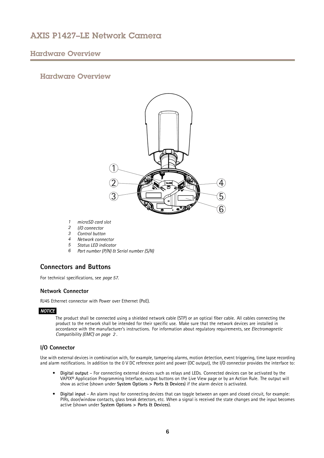
Connectivity is also a major highlight of the P1427-LE. With Power over Ethernet (PoE), the installation process is simplified, as both power and data can be transmitted through a single cable. This feature not only reduces installation costs but also enhances flexibility in positioning the camera.
In conclusion, the Axis Communications P1427-LE is a versatile and high-performance network camera that excels in various applications. Its combination of superior image quality, robust durability, advanced analytics, and user-friendly installation makes it an invaluable tool for enhancing security and ensuring reliable surveillance in any setting. Whether used for commercial, industrial, or public safety applications, the P1427-LE stands out as a leader in modern surveillance technology.