AXIS P5522 PTZ Dome Network Camera
Multi-Connector Cable (sold separately)
When connecting external equipment to the Axis product, a
Connect the
7 . The cable provides the following connectors:
Power connector -
Audio in (pink) - 3.5 mm input for a mono microphone, or a
Audio out (green) - 3.5 mm output for audio (line level) that can be connected to a public address (PA) system or an active speaker with a
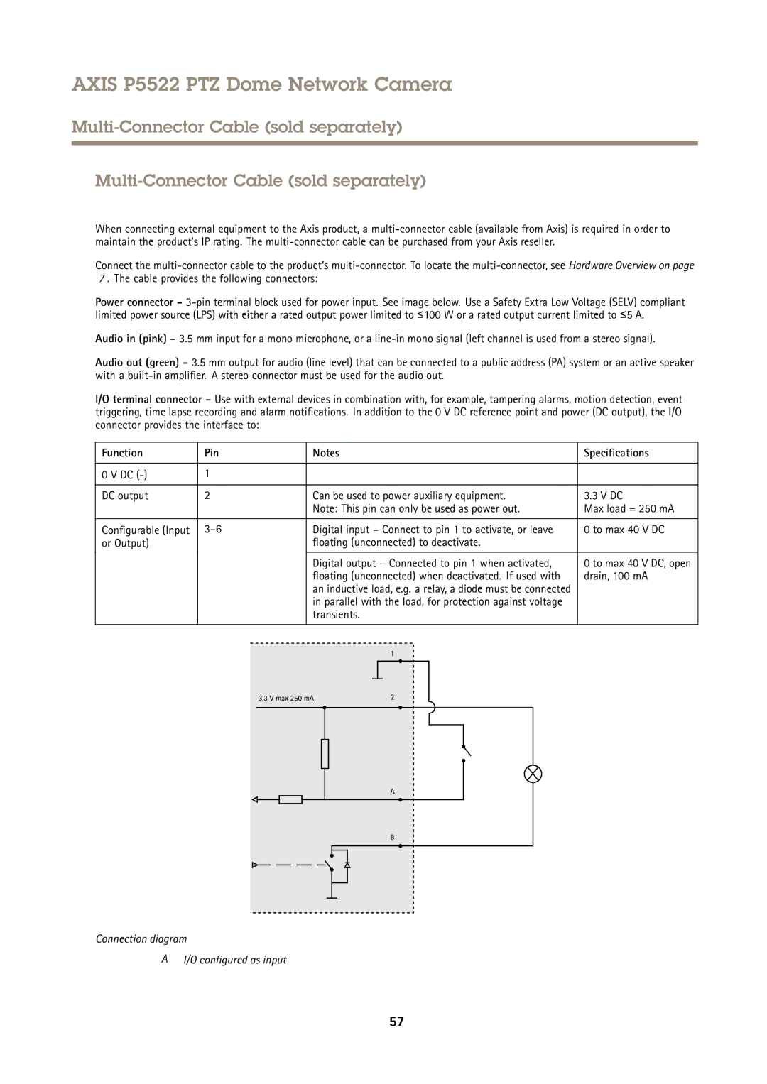
I/O terminal connector - Use with external devices in combination with, for example, tampering alarms, motion detection, event triggering, time lapse recording and alarm notifications. In addition to the 0 V DC reference point and power (DC output), the I/O connector provides the interface to:
Function | Pin | Notes | Specifications | |||||||||||||||||
|
|
|
|
|
|
|
|
|
|
|
|
|
|
|
|
|
|
|
|
|
0 V DC | 1 |
|
|
|
|
|
|
|
|
|
|
|
|
|
|
|
|
|
|
|
|
|
|
|
|
|
|
|
|
|
|
|
|
|
|
|
|
|
|
|
|
DC output | 2 |
|
|
|
|
| Can be used to power auxiliary equipment. | 3.3 V DC | ||||||||||||
|
|
|
|
|
|
| Note: This pin can only be used as power out. | Max load = 250 mA | ||||||||||||
|
|
|
|
|
|
|
|
|
|
|
|
|
|
|
|
|
|
|
|
|
Configurable (Input | Digital input – Connect to pin 1 to activate, or leave | 0 to max 40 V DC | ||||||||||||||||||
or Output) |
|
|
|
|
|
| floating (unconnected) to deactivate. |
| ||||||||||||
|
|
|
|
|
|
|
|
|
|
|
|
|
|
|
|
|
|
|
|
|
|
|
|
|
|
|
| Digital output – Connected to pin 1 when activated, | 0 to max 40 V DC, open | ||||||||||||
|
|
|
|
|
|
| floating (unconnected) when deactivated. If used with | drain, 100 mA | ||||||||||||
|
|
|
|
|
|
| an inductive load, e.g. a relay, a diode must be connected |
| ||||||||||||
|
|
|
|
|
|
| in parallel with the load, for protection against voltage |
| ||||||||||||
|
|
|
|
|
|
| transients. |
| ||||||||||||
|
|
|
|
|
|
|
|
|
|
|
|
|
|
|
|
|
|
|
|
|
|
|
|
|
|
|
|
|
|
|
|
|
|
|
|
|
|
|
|
|
|
|
|
|
|
|
|
|
|
|
|
|
|
|
|
|
|
|
|
|
|
|
|
|
|
|
|
|
|
|
|
|
|
|
|
|
|
|
|
|
|
|
|
|
|
|
|
|
|
|
|
|
|
|
|
|
|
|
|
|
|
|
|
|
|
|
|
|
|
|
|
|
|
|
|
|
|
|
|
|
|
|
|
|
|
|
|
|
|
|
|
|
|
|
|
|
|
|
|
|
|
|
|
|
|
|
|
|
|
|
|
|
|
|
|
|
|
|
|
|
|
|
|
|
|
|
|
|
|
|
|
|
|
|
|
|
|
|
|
|
|
|
|
|
|
|
|
|
|
|
|
|
|
|
|
|
|
|
|
|
|
|
|
|
|
|
|
|
|
|
|
|
|
|
|
|
|
|
|
|
|
|
|
|
|
|
|
|
|
|
|
|
|
|
|
|
|
|
|
|
|
|
|
|
|
|
|
|
|
|
|
|
|
|
|
|
|
|
|
|
|
|
|
|
|
|
|
|
|
|
|
|
Connection diagram
A I/O configured as input
57