9
8
23
20
4
6
3
22
18
7
5
19 21
1
17
|
| 2 |
|
|
| 12 |
|
|
| 11 |
|
28 |
|
| 16 |
| 26 | 13 | |
| 14 | ||
|
|
| |
|
| 15 |
|
25 + | - | Belt Clip |
|
2424
-+
10
27
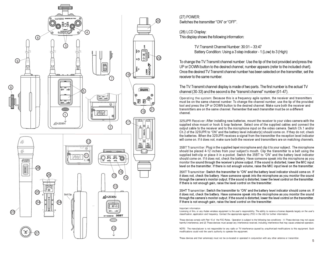
(27) POWER:
Switches the transmitter “ON” or “OFF”.
(28) LCD Display:
This display shows the following information:
TV:Transmit Channel Number: 30:01 – 33:47
Battery Condition: Using a 3 step indicator - 1 (Low) to 3 (High)
To change the TV:Transmit channel number: Use the tip of the tool provided and press the UP or DOWN button to the desired channel, number appears (refer to the included chart). Once the desired TV:Transmit channel number has been selected on the transmitter, set the receiver to the same number.
The TV:Transmit channel display is made of two parts. The first number is the actual TV channel
Operating the system: Because this is a frequency agile system, the receiver and transmitters must be on the same channel number. To change the channel number, use the tip of the provided tool and press the UP or DOWN button to the desired channel. Make sure both the receiver and transmitters are on the same channel. Remember that each transmitter must be on a different channel.
325UPR Receiver: After installing new batteries, mount the receiver to your video camera with the supplied shoe mount or hook & loop fastener. Select one of the supplied cables and connect the output cable to the receiver and to the microphone input on the video camera. Switch Ch.1 and/or Ch.2 of the 325UPR to “ON” and the battery level indicator(s) should come on. If they do not, check the batteries. When the 325UPR receives a signal from the transmitter the reception level indicator will come on. If it does not, make sure both the receiver and transmitters are on matching channels.
35BT Transmitter: Plug in the supplied lapel microphone and clip it to your subject. The microphone should be placed
35XT Transmitter: Switch the transmitter to “ON” and the battery level indicator should come on. If it does not, check the battery. Have someone speak into the microphone as you monitor the sound through the camera’s monitor output. If the sound is distorted, lower the level control on the transmitter. If there is not enough gain, raise the level control on the transmitter.
35HT Transmitter: Switch the transmitter to “ON” and the battery level indicator should come on. If it does not, check the battery. Have someone speak into the microphone as you monitor the sound through the camera’s monitor output. If the sound is distorted, lower the level control on the transmitter. If there is not enough gain, raise the level control on the transmitter.
Important information
Licensing of this, or any Azden wireless equipment is the user’s responsibility. The ability to receive a license depends largely on the user’s classification, application and frequency. Contact the appropriate agency (FCC in the US) for further information.
These devices comply with Part 15 of the FCC Rules. Operation is subject to the following two conditions: (1) These devices may not cause harmful interference, and (2) These devices must accept any interference received, including interference that may cause undesired operation.
NOTE: The manufacturer is not responsible for any radio or TV interference caused by unauthorized modifications to this equipment. Such modifications could void the user's authority to operate the equipment.
These devices and their antenna(s) must not be
5
