PLACING THE TOOL IN SERVICE
ADJUSTMENTS | NOT allow the tool to react against the hoses, swivels, | |
| or inlets. | |
SETTING THE TORQUE | 3. After having turned the Pump on and presetting the | |
pressure for the correct torque, depress the remote | ||
After determining the desired torque, use the torque con- | ||
control button to advance the Piston Assembly. If the | ||
version chart on the Shroud or the torque conversion | ||
notch in the piston rod did not engage the Retract Pin in | ||
charts on pages 5 and 6 to determine the pressure that is | ||
the Ratchet Link when the Link was joined to the | ||
necessary to achieve that torque. | ||
Housing, it will engage the Pin automatically during the | ||
1. Connect the tool to the power supply and turn the | ||
first advance stroke. | ||
pump on. | ||
4. When the Link is connected to the Housing and the | ||
2. Depress the remote control button causing the | ||
wrench is started, the reaction surface of the wrench will | ||
pressure to be shown on the gauge. | ||
move against the contact point and the nut will begin to | ||
3. Adjust the pressure by loosening the wing nut that | ||
turn. | ||
locks the pressure adjustment thumbscrew. Rotate the | ||
5. When the nut is no longer turning and the Pump | ||
thumbscrew clockwise to increase the pressure and | ||
Gauge reaches the preset pressure, release the remote | ||
counterclockwise to decrease the pressure. When | ||
control button. The piston rod will retract when the | ||
decreasing pressure, always lower the pressure below the | ||
button is released and under normal conditions, an | ||
desired point and then bring the gauge back up to the | ||
audible “click” will be heard as the tool resets itself. | ||
desired pressure. | ||
6. Continue to cycle the tool until it “stalls” and the | ||
4.When the desired pressure is reached, retighten the | ||
preset psi/torque has been attained. | ||
wing nut and cycle the tool again to confirm that the | ||
7. Once the nut stops rotating, cycle the tool one last | ||
desired pressure setting has been obtained. | ||
time to achieve total torque. | ||
|
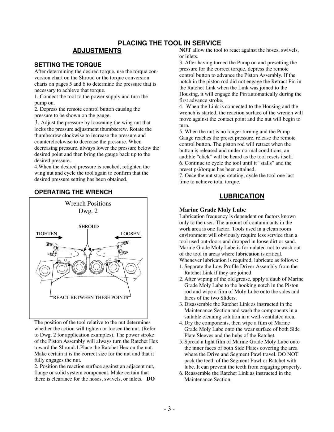
OPERATING THE WRENCH
Wrench Positions |
|
|
Dwg. 2 |
| Marine Grade Moly Lube |
|
| Lubrication frequency is dependent on factors known |
SHROUD |
| only to the user. The amount of contaminants in the |
| work area is one factor. Tools used in a clean room | |
|
| |
TIGHTEN | LOOSEN | environment will obviously require less service than a |
|
| |
|
| tool used |
|
| Marine Grade Moly Lube is formulated not to wash out |
|
| of the tool in areas where lubrication is critical. |
|
| Whenever lubrication is required, lubricate as follows: |
|
| 1. Separate the Low Profile Driver Assembly from the |
|
| Ratchet Link if they are joined. |
|
| 2. After wiping of the old grease, apply a daub of Marine |
|
| Grade Moly Lube to the hooking notch in the Piston |
|
| rod and wipe a film of Moly Lube onto the sides and |
REACT BETWEEN THESE POINTS | faces of the two Sliders. | |
|
| 3. Disassemble the Ratchet Link as instructed in the |
|
| Maintenance Section and wash the components in a |
|
| suitable cleaning solution in a |
The position of the tool relative to the nut determines | 4. Dry the components, then wipe a film of Marine | |
whether the action will tighten or loosen the nut. (Refer | Grade Moly Lube onto the wear surface of both Side | |
to Dwg. 2 for application examples). The power stroke | Plate Sleeves and the hubs of the Ratchet. | |
of the Piston Assembly will always turn the Ratchet Hex | 5. Spread a light film of Marine Grade Moly Lube onto | |
toward the Shroud.1.Place the Ratchet Hex on the nut. | the inner faces of both Side Plates covering the area | |
Make certain it is the correct size for the nut and that it | where the Drive and Segment Pawl travel. DO NOT | |
fully engages the nut. |
| pack the teeth of the Segment Pawl or Ratchet with |
2. Position the reaction surface against an adjacent nut, | lube. It can prevent the teeth from engaging properly. | |
flange or solid system component. Make certain that | 6. Reassemble the Ratchet Link as instructed in the | |
there is clearance for the hoses, swivels, or inlets. DO | Maintenance Section. | |
- 3 -