B&B Electronics 2011 manual Installation, Connecting The Asynchronous Port

Models: 2011

1 11
Download 11 pages 7.14 Kb
Page 7
Image 7
4.0 INSTALLATION

4.0 INSTALLATION

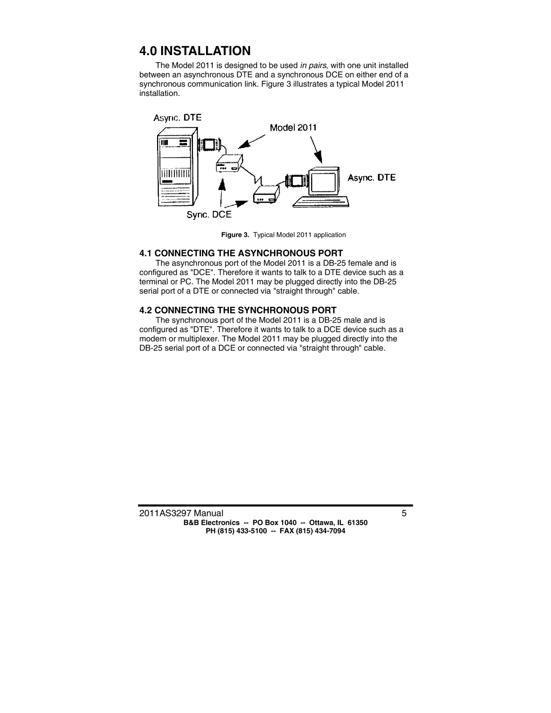
The Model 2011 is designed to be used in pairs, with one unit installed between an asynchronous DTE and a synchronous DCE on either end of a synchronous communication link. Figure 3 illustrates a typical Model 2011 installation.

Figure 3. Typical Model 2011 application

4.1 CONNECTING THE ASYNCHRONOUS PORT

The asynchronous port of the Model 2011 is a DB-25 female and is configured as "DCE". Therefore it wants to talk to a DTE device such as a terminal or PC. The Model 2011 may be plugged directly into the DB-25 serial port of a DTE or connected via "straight through" cable.

4.2 CONNECTING THE SYNCHRONOUS PORT

The synchronous port of the Model 2011 is a DB-25 male and is configured as "DTE". Therefore it wants to talk to a DCE device such as a modem or multiplexer. The Model 2011 may be plugged directly into the DB-25 serial port of a DCE or connected via "straight through" cable.

2011AS3297 Manual

5

B&B Electronics -- PO Box 1040 -- Ottawa, IL 61350

PH (815) 433-5100 -- FAX (815) 434-7094

Page 7
Image 7
B&B Electronics 2011 manual Installation, Connecting The Asynchronous Port, Connecting The Synchronous Port