This chapter will explain "HIGH" and "LOW" states and show some general examples of how to interface to the I/O lines. Caution must be taken not to exceed 232DRIO specifications listed in Chapter 1 when interfacing to external devices. Failure to stay within these specifications could result in damage to the unit and will void warranty.
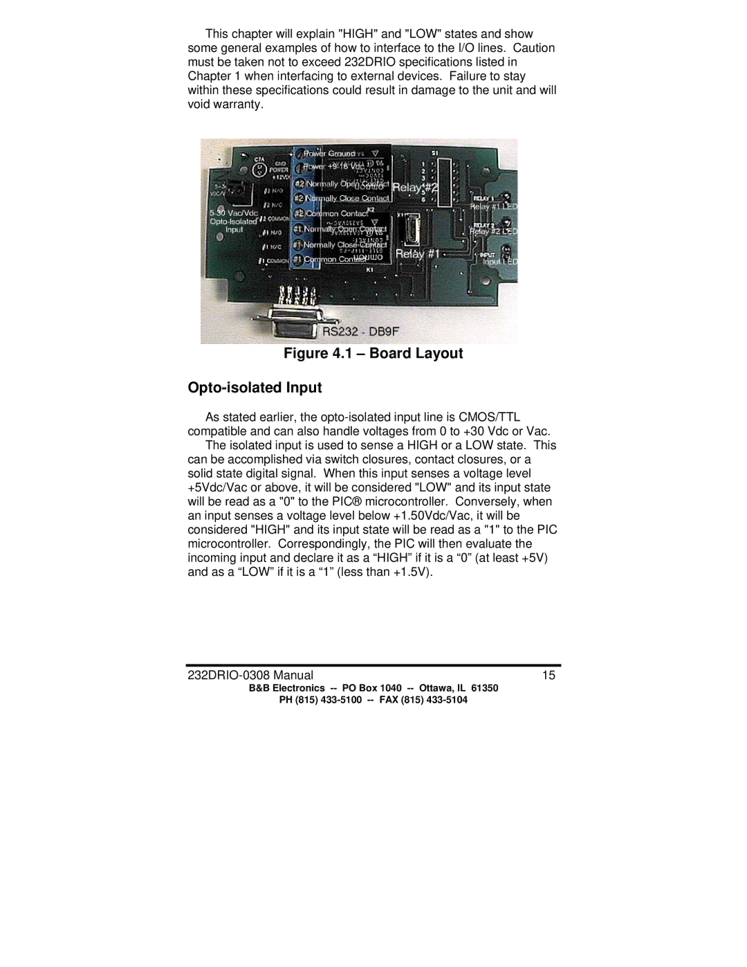
Figure 4.1 – Board Layout
Opto-isolated Input
As stated earlier, the
The isolated input is used to sense a HIGH or a LOW state. This can be accomplished via switch closures, contact closures, or a solid state digital signal. When this input senses a voltage level +5Vdc/Vac or above, it will be considered "LOW" and its input state will be read as a "0" to the PIC® microcontroller. Conversely, when an input senses a voltage level below +1.50Vdc/Vac, it will be considered "HIGH" and its input state will be read as a "1" to the PIC microcontroller. Correspondingly, the PIC will then evaluate the incoming input and declare it as a “HIGH” if it is a “0” (at least +5V) and as a “LOW” if it is a “1” (less than +1.5V).
15 |
B&B Electronics
PH (815)
