Example 3.1 | Set Output Lines |
| |||
| Data Byte |
| Relays |
| |
Binary | Decimal | Hex | Relay #2 | Relay #1 | |
XXXXXX00 |
| 0 | 0 | ||
XXXXXX01 |
| 1 | 1 | energized | |
XXXXXX10 |
| 2 | 2 | energized | |
XXXXXX11 |
| 3 | 3 | energized | energized |
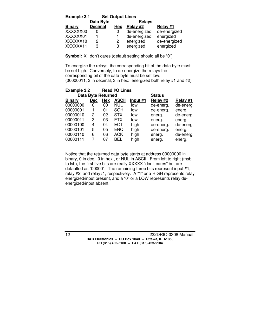
Symbol: X don’t cares (default setting should all be “0”)
To energize the relays, the corresponding bit of the data byte must be set high. Conversely, to
(00000011, 3 in decimal, 3 in hex: energized both relay #1 and #2)
Example 3.2 | Read I/O Lines |
|
| |||
Data Byte Returned |
| Status |
| |||
Binary | Dec | Hex | ASCII | Input #1 | Relay #2 | Relay #1 |
00000000 | 0 | 00 | NUL | low | ||
00000001 | 1 | 01 | SOH | low | energ. | |
00000010 | 2 | 02 | STX | low | energ. | |
00000011 | 3 | 03 | ETX | low | energ. | energ. |
00000100 | 4 | 04 | EOT | high | ||
00000101 | 5 | 05 | ENQ | high | energ. | |
00000110 | 6 | 06 | ACK | high | energ. | |
00000111 | 7 | 07 | BEL | high | energ. | energ. |
Notice that the returned data byte starts at address 00000000 in binary, 0 in dec., 0 in hex., or NUL in ASCII. From left to right (msb to lsb), the first five bits are really XXXXX “don’t cares” but are defaulted as “00000”. The remaining three bits represent input #1, relay #2, and relay#1, respectively. A “1” or a HIGH represents relay energized/input present, and a “0” or a LOW represents relay de- energized/input absent.
12 | |
B&B Electronics | PO Box 1040 |
PH (815)
