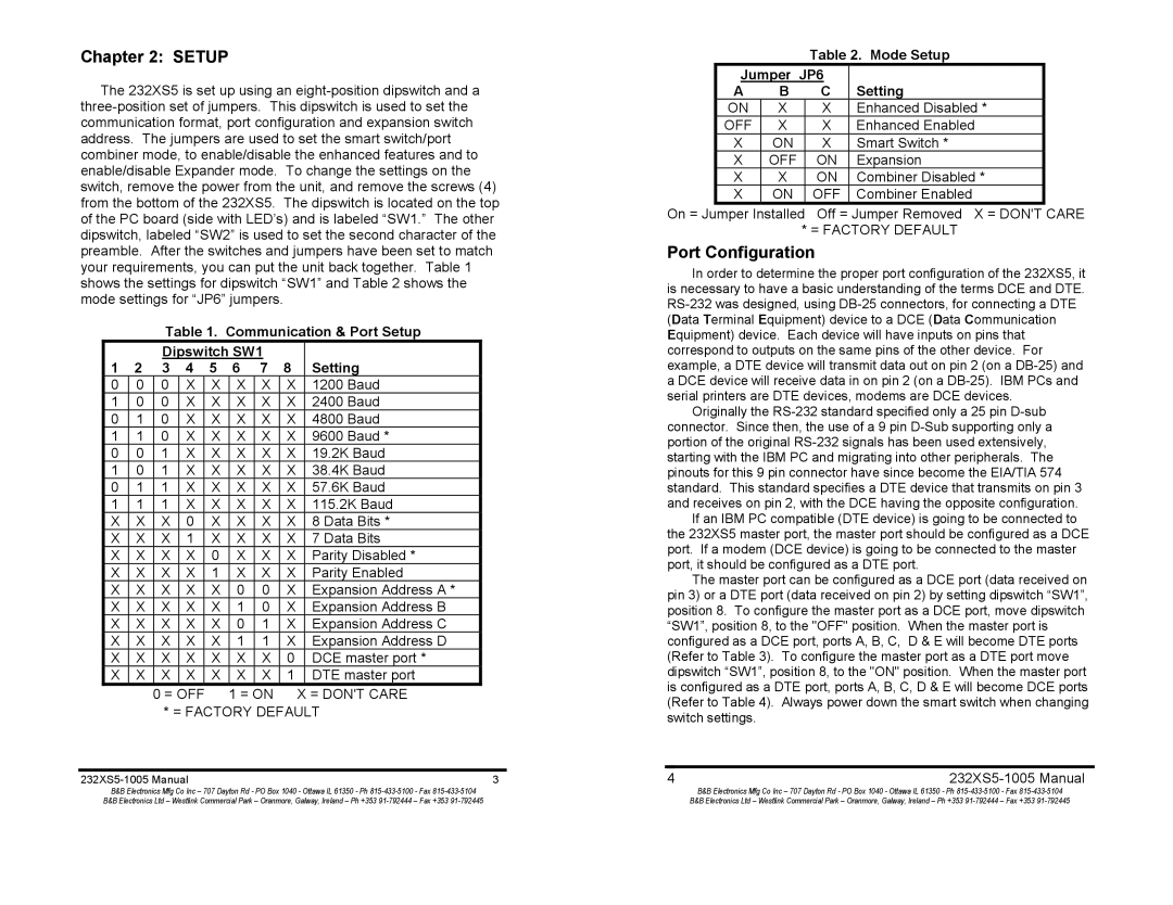
B&B Electronics 232XS5 manual Port Configuration, Mode Setup Jumper JP6 Setting

Models: 232XS5

1 15
Download 15 pages 58.41 Kb
Page 4
Image 4

Chapter 2: SETUP

The 232XS5 is set up using an eight-position dipswitch and a three-position set of jumpers. This dipswitch is used to set the communication format, port configuration and expansion switch address. The jumpers are used to set the smart switch/port combiner mode, to enable/disable the enhanced features and to enable/disable Expander mode. To change the settings on the switch, remove the power from the unit, and remove the screws (4) from the bottom of the 232XS5. The dipswitch is located on the top of the PC board (side with LED’s) and is labeled “SW1.” The other dipswitch, labeled “SW2” is used to set the second character of the preamble. After the switches and jumpers have been set to match your requirements, you can put the unit back together. Table 1 shows the settings for dipswitch “SW1” and Table 2 shows the mode settings for “JP6” jumpers.

Table 1. Communication & Port Setup


Dipswitch SW1


1

2

3

4

5

6

7

8

Setting

0

0

0

X

X

X

X

X

1200 Baud

1

0

0

X

X

X

X

X

2400 Baud

0

1

0

X

X

X

X

X

4800 Baud

1

1

0

X

X

X

X

X

9600 Baud *

0

0

1

X

X

X

X

X

19.2K Baud

1

0

1

X

X

X

X

X

38.4K Baud

0

1

1

X

X

X

X

X

57.6K Baud

1

1

1

X

X

X

X

X

115.2K Baud

X

X

X

0

X

X

X

X

8 Data Bits *

X

X

X

1

X

X

X

X

7 Data Bits

X

X

X

X

0

X

X

X

Parity Disabled *

X

X

X

X

1

X

X

X

Parity Enabled

X

X

X

X

X

0

0

X

Expansion Address A *

X

X

X

X

X

1

0

X

Expansion Address B

X

X

X

X

X

0

1

X

Expansion Address C

X

X

X

X

X

1

1

X

Expansion Address D

X

X

X

X

X

X

X

0

DCE master port *

X

X

X

X

X

X

X

1

DTE master port

0 = OFF 1 = ON

X = DON'T CARE

* = FACTORY DEFAULT


232XS5-1005 Manual

3

B&B Electronics Mfg Co Inc – 707 Dayton Rd - PO Box 1040 - Ottawa IL 61350 - Ph 815-433-5100 - Fax 815-433-5104

B&B Electronics Ltd – Westlink Commercial Park – Oranmore, Galway, Ireland – Ph +353 91-792444 – Fax +353 91-792445

Table 2. Mode Setup


Jumper JP6


A

B

C

Setting


ON

X

X

Enhanced Disabled *


OFF

X

X

Enhanced Enabled


X

ON

X

Smart Switch *


X

OFF

ON

Expansion


X

X

ON

Combiner Disabled *


X

ON

OFF

Combiner Enabled


On = Jumper Installed

Off = Jumper Removed X = DON'T

CARE


* = FACTORY DEFAULT

Port Configuration

In order to determine the proper port configuration of the 232XS5, it is necessary to have a basic understanding of the terms DCE and DTE. RS-232 was designed, using DB-25 connectors, for connecting a DTE (Data Terminal Equipment) device to a DCE (Data Communication Equipment) device. Each device will have inputs on pins that correspond to outputs on the same pins of the other device. For example, a DTE device will transmit data out on pin 2 (on a DB-25) and a DCE device will receive data in on pin 2 (on a DB-25). IBM PCs and serial printers are DTE devices, modems are DCE devices.

Originally the RS-232 standard specified only a 25 pin D-sub connector. Since then, the use of a 9 pin D-Sub supporting only a portion of the original RS-232 signals has been used extensively, starting with the IBM PC and migrating into other peripherals. The pinouts for this 9 pin connector have since become the EIA/TIA 574 standard. This standard specifies a DTE device that transmits on pin 3 and receives on pin 2, with the DCE having the opposite configuration.

If an IBM PC compatible (DTE device) is going to be connected to the 232XS5 master port, the master port should be configured as a DCE port. If a modem (DCE device) is going to be connected to the master port, it should be configured as a DTE port.

The master port can be configured as a DCE port (data received on pin 3) or a DTE port (data received on pin 2) by setting dipswitch “SW1”, position 8. To configure the master port as a DCE port, move dipswitch “SW1”, position 8, to the "OFF" position. When the master port is configured as a DCE port, ports A, B, C, D & E will become DTE ports (Refer to Table 3). To configure the master port as a DTE port move dipswitch “SW1”, position 8, to the "ON" position. When the master port is configured as a DTE port, ports A, B, C, D & E will become DCE ports (Refer to Table 4). Always power down the smart switch when changing switch settings.

4232XS5-1005 Manual

B&B Electronics Mfg Co Inc – 707 Dayton Rd - PO Box 1040 - Ottawa IL 61350 - Ph 815-433-5100 - Fax 815-433-5104

B&B Electronics Ltd – Westlink Commercial Park – Oranmore, Galway, Ireland – Ph +353 91-792444 – Fax +353 91-792445

Page 4
Image 4
B&B Electronics 232XS5 manual Port Configuration, Communication & Port Setup Dipswitch SW1 Setting

232XS5 specifications

B&B Electronics 232XS5 is a state-of-the-art Five Port Expandable Smart Switch, designed to provide businesses with enhanced connectivity options and efficient network management. This robust switch addresses the growing needs for high-performance networking in various applications, including industrial, commercial, and residential settings.

One of the main features of the 232XS5 is its ability to expand with additional ports. Users can easily increase their connectivity by adding more devices as their network requirements change, which ensures a future-proof solution without the need for a complete system overhaul. This flexibility makes it an ideal choice for organizations anticipating growth or changes in their networking needs.

The switch supports a range of advanced technologies designed to optimize performance. With its Layer 2 switching capabilities, the 232XS5 can efficiently manage data traffic, ensuring smoother communication between connected devices. Its support for auto-negotiation and auto-MDIX simplifies installations, automatically configuring each port to the appropriate speed and cable type, thereby reducing setup time and potential errors.

Another notable characteristic of the 232XS5 is its robust security features. The smart switch includes VLAN support, which allows network administrators to segment traffic and enhance security by isolating sensitive data transmissions. Additionally, it supports port security features, enabling organizations to restrict access to specific devices, thus preventing unauthorized access and potential breaches.

Energy efficiency is also a key component of the B&B Electronics 232XS5. The switch employs energy-saving technologies that reduce power consumption without compromising performance. This not only lowers operational costs but also supports sustainability initiatives, making it a responsible choice for environmentally-conscious businesses.

Furthermore, the switch's compact design and solid construction ensure durability in demanding environments. Whether deployed in an office space or an industrial setting, the 232XS5 is built to withstand various conditions, ensuring reliable operation over time.

Overall, the B&B Electronics 232XS5 Five Port Expandable Smart Switch combines flexibility, advanced features, and robust security, making it a compelling solution for any organization looking to enhance its networking capabilities. With its easy expandability and commitment to energy efficiency, it is a smart investment for the future of networking.