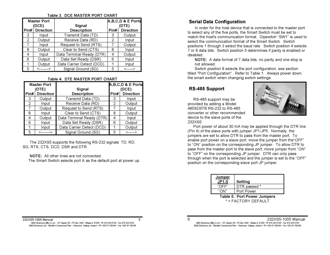
Table 3. DCE MASTER PORT CHART

Master Port

Signal

A,B,C,D & E Ports


(DCE)


(DTE)

Pin#

Direction

Description

Pin#

Direction

3

Input

Transmit Data (TD)

3

Output

2

Output

Receive Data (RD)

2

Input

7

Input

Request to Send (RTS)

7

Output

8

Output

Clear to Send (CTS)

8

Input

4

Input

Data Terminal Ready (DTR)

4

Output

6

Output

Data Set Ready (DSR)

6

Input

1

Output

Data Carrier Detect (DCD)

1

Input

5

<------->

Signal Ground (SG)

5

<----->

Table 4. DTE MASTER PORT CHART

Master Port

Signal

A,B,C,D & E Ports


(DTE)


(DCE)

Pin#

Direction

Description

Pin#

Direction

3

Output

Transmit Data (TD)

3

Input

2

Input

Receive Data (RD)

2

Output

7

Output

Request to Send (RTS)

7

Input

8

Input

Clear to Send (CTS)

8

Output

4

Output

Data Terminal Ready (DTR)

4

Input

6

Input

Data Set Ready (DSR)

6

Output

1

Input

Data Carrier Detect (DCD)

1

Output

5

<------->

Signal Ground (SG)

5

<----->

The 232XS5 supports the following RS-232 signals: TD, RD, SG, RTS, CTS, DCD, DSR and DTR.

NOTE: All other lines are not connected.

The Smart Switch selects port A as the default port at power up.

232XS5-1005 Manual

5

B&B Electronics Mfg Co Inc – 707 Dayton Rd - PO Box 1040 - Ottawa IL 61350 - Ph 815-433-5100 - Fax 815-433-5104

B&B Electronics Ltd – Westlink Commercial Park – Oranmore, Galway, Ireland – Ph +353 91-792444 – Fax +353 91-792445

Serial Data Configuration

In order for the host device that is connected to the master port to select any of the five ports, the Smart Switch must be set to match the host's communication format. Dipswitch “SW1” is used to select the communication format of the Smart Switch. Switch positions 1 through 3 select the baud rate. Switch position 4 selects 7 or 8 data bits. Switch position 5 determines if parity is enabled or disabled.

NOTE: A data format of 7 data bits, no parity and one stop is not allowed.

Switch position 8 selects the port configuration, see section titled "Port Configuration". Refer to Table 1. Always power down the smart switch when changing switch settings.

RS-485 Support

RS-485 support may be provided by adding a Model 485SD9TB RS-232 to RS-485 converter or other recommended device to the slave ports of the 232XS5.

Port power of about 30 mA may be applied through the DTR line (Pin 4) of the slave ports with jumper JP1-JP5. Normally, the jumpers are set to allow DTR to pass from the master port. To enable port power on a slave port, move the jumper from the“OFF” to “ON” position on the corresponding JP jumper. To allow DTR to pass from the master port to the slave port, move jumper from “ON” to “OFF” on the corresponding JP jumper. DTR can only pass through when the port is selected and the jumper is set to the “OFF” position on the corresponding slave port JP jumper.

Jumper

Setting

JP1-5

“OFF”

DTR passed *

“ON”

Port Power


Table 5. Port Power Jumpers


* = FACTORY DEFAULT


6

232XS5-1005 Manual


B&B Electronics Mfg Co Inc – 707 Dayton Rd - PO Box 1040 - Ottawa IL 61350 - Ph 815-433-5100 - Fax 815-433-5104


B&B Electronics Ltd – Westlink Commercial Park – Oranmore, Galway, Ireland – Ph +353 91-792444 – Fax +353 91-792445

Page 5
Image 5
B&B Electronics 232XS5 manual Serial Data Configuration, RS-485 Support, Dce Dte, Dte Dce

232XS5 specifications

B&B Electronics 232XS5 is a state-of-the-art Five Port Expandable Smart Switch, designed to provide businesses with enhanced connectivity options and efficient network management. This robust switch addresses the growing needs for high-performance networking in various applications, including industrial, commercial, and residential settings.

One of the main features of the 232XS5 is its ability to expand with additional ports. Users can easily increase their connectivity by adding more devices as their network requirements change, which ensures a future-proof solution without the need for a complete system overhaul. This flexibility makes it an ideal choice for organizations anticipating growth or changes in their networking needs.

The switch supports a range of advanced technologies designed to optimize performance. With its Layer 2 switching capabilities, the 232XS5 can efficiently manage data traffic, ensuring smoother communication between connected devices. Its support for auto-negotiation and auto-MDIX simplifies installations, automatically configuring each port to the appropriate speed and cable type, thereby reducing setup time and potential errors.

Another notable characteristic of the 232XS5 is its robust security features. The smart switch includes VLAN support, which allows network administrators to segment traffic and enhance security by isolating sensitive data transmissions. Additionally, it supports port security features, enabling organizations to restrict access to specific devices, thus preventing unauthorized access and potential breaches.

Energy efficiency is also a key component of the B&B Electronics 232XS5. The switch employs energy-saving technologies that reduce power consumption without compromising performance. This not only lowers operational costs but also supports sustainability initiatives, making it a responsible choice for environmentally-conscious businesses.

Furthermore, the switch's compact design and solid construction ensure durability in demanding environments. Whether deployed in an office space or an industrial setting, the 232XS5 is built to withstand various conditions, ensuring reliable operation over time.

Overall, the B&B Electronics 232XS5 Five Port Expandable Smart Switch combines flexibility, advanced features, and robust security, making it a compelling solution for any organization looking to enhance its networking capabilities. With its easy expandability and commitment to energy efficiency, it is a smart investment for the future of networking.