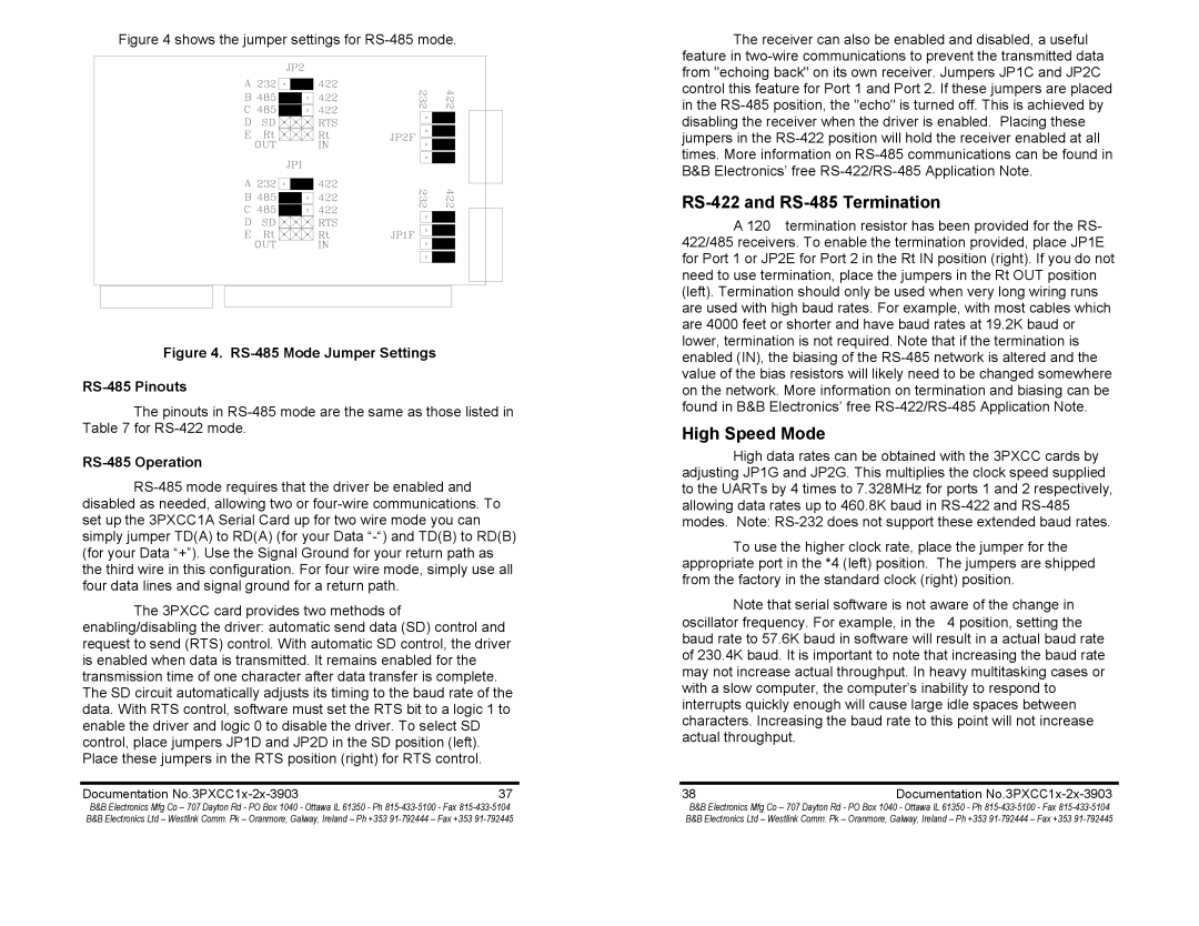
Figure 4 shows the jumper settings for RS-485 mode.
Figure 4. RS-485 Mode Jumper Settings
RS-485 Pinouts
The pinouts in
RS-485 Operation
The 3PXCC card provides two methods of enabling/disabling the driver: automatic send data (SD) control and request to send (RTS) control. With automatic SD control, the driver is enabled when data is transmitted. It remains enabled for the transmission time of one character after data transfer is complete. The SD circuit automatically adjusts its timing to the baud rate of the data. With RTS control, software must set the RTS bit to a logic 1 to enable the driver and logic 0 to disable the driver. To select SD control, place jumpers JP1D and JP2D in the SD position (left). Place these jumpers in the RTS position (right) for RTS control.
Documentation | 37 |
The receiver can also be enabled and disabled, a useful feature in
RS-422 and RS-485 Termination
A 120Ω termination resistor has been provided for the RS- 422/485 receivers. To enable the termination provided, place JP1E for Port 1 or JP2E for Port 2 in the Rt IN position (right). If you do not need to use termination, place the jumpers in the Rt OUT position (left). Termination should only be used when very long wiring runs are used with high baud rates. For example, with most cables which are 4000 feet or shorter and have baud rates at 19.2K baud or lower, termination is not required. Note that if the termination is enabled (IN), the biasing of the
High Speed Mode
High data rates can be obtained with the 3PXCC cards by adjusting JP1G and JP2G. This multiplies the clock speed supplied to the UARTs by 4 times to 7.328MHz for ports 1 and 2 respectively, allowing data rates up to 460.8K baud in
To use the higher clock rate, place the jumper for the appropriate port in the *4 (left) position. The jumpers are shipped from the factory in the standard clock (right) position.
Note that serial software is not aware of the change in oscillator frequency. For example, in the × 4 position, setting the baud rate to 57.6K baud in software will result in a actual baud rate of 230.4K baud. It is important to note that increasing the baud rate may not increase actual throughput. In heavy multitasking cases or with a slow computer, the computer’s inability to respond to interrupts quickly enough will cause large idle spaces between characters. Increasing the baud rate to this point will not increase actual throughput.
38 | Documentation |
B&B Electronics Mfg Co – 707 Dayton Rd - PO Box 1040 - Ottawa IL 61350 - Ph | B&B Electronics Mfg Co – 707 Dayton Rd - PO Box 1040 - Ottawa IL 61350 - Ph |
B&B Electronics Ltd – Westlink Comm. Pk – Oranmore, Galway, Ireland – Ph +353 | B&B Electronics Ltd – Westlink Comm. Pk – Oranmore, Galway, Ireland – Ph +353 |