Chapter 3: OPERATION
Communicating with the WDT
The WDT uses a
Regardless of the mode of operation of the WDT, a "1" must be written to the least significant bit of the latch to start the timers. Writing a "0" to the least significant bit of the latch at any time will stop the timers. Note that since the least significant bit is used to start and stop the counters, any even number written to the latch will result in the counters being turned off.
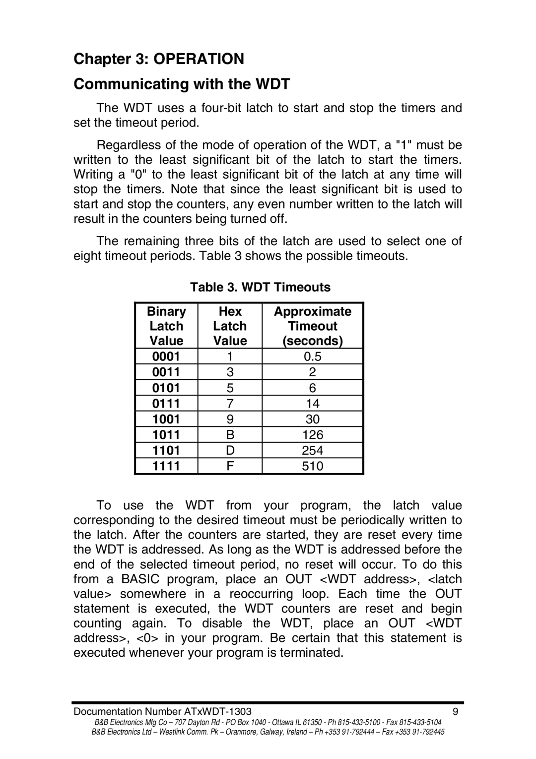
The remaining three bits of the latch are used to select one of eight timeout periods. Table 3 shows the possible timeouts.
Table 3. WDT Timeouts
Binary | Hex | Approximate |
Latch | Latch | Timeout |
Value | Value | (seconds) |
0001 | 1 | 0.5 |
0011 | 3 | 2 |
0101 | 5 | 6 |
0111 | 7 | 14 |
1001 | 9 | 30 |
1011 | B | 126 |
1101 | D | 254 |
1111 | F | 510 |
To use the WDT from your program, the latch value corresponding to the desired timeout must be periodically written to the latch. After the counters are started, they are reset every time the WDT is addressed. As long as the WDT is addressed before the end of the selected timeout period, no reset will occur. To do this from a BASIC program, place an OUT <WDT address>, <latch value> somewhere in a reoccurring loop. Each time the OUT statement is executed, the WDT counters are reset and begin counting again. To disable the WDT, place an OUT <WDT address>, <0> in your program. Be certain that this statement is executed whenever your program is terminated.
Documentation Number | 9 |
B&B Electronics Mfg Co – 707 Dayton Rd - PO Box 1040 - Ottawa IL 61350 - Ph