The four bit latch values are also readable. Reading these bits is recommended to verify the presence and setup of the WDT. The BASIC command INP <WDTaddress> is used to read from the WDT. The top three bits are not used and can be masked out. In the ATRWDT the fifth bit is the reset flag. It will be a 1 when the ATRWDT resets the computer and a 0 if the computer has not been reset by the ATRWDT. This bit will be cleared if the computer is turned off or after the bit has been read. A small example program, written in QuickBASIC can be found in Appendix B.
Table 4. Registers
Write Register | Read Register |
L0 | L0 |
L1 | L1 |
L2 | L2 |
L3 | L3 |
X | Reset Flag FOR ATR |
| X FOR ATX |
X | X |
X | X |
X | X |
X = Don’t Care
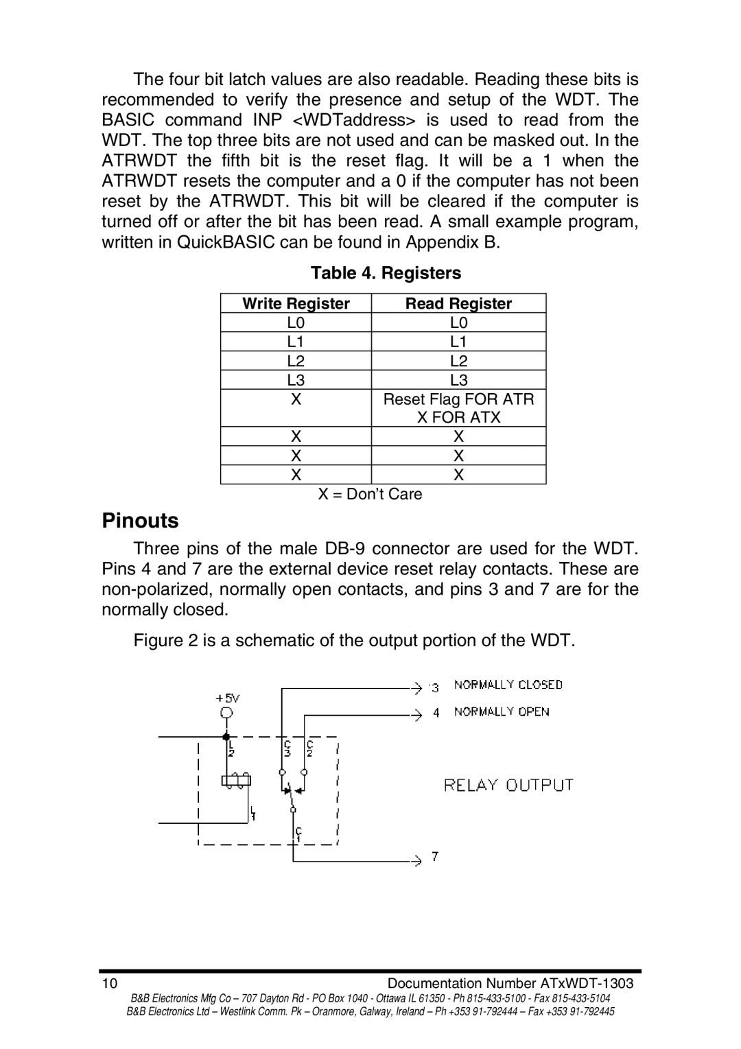
Pinouts
Three pins of the male
Figure 2 is a schematic of the output portion of the WDT.
10 | Documentation Number |
B&B Electronics Mfg Co – 707 Dayton Rd - PO Box 1040 - Ottawa IL 61350 - Ph