Contents
Model 232BSS4
Buffered Smart Switch
This product designed and manufactured in Ottawa, Illinois USA
of domestic and imported parts by
Page
CHAPTER 4 SETUP SOFTWARE
Table of Contents
APPENDIX B CABLE CHARTS
APPENDIX C BLOCK DIAGRAM
Documentation Number 232BSS4-2907m
Documentation Number 232BSS4-2907m
Chapter 1 - Introduction
Default Parameters
Specifications
1. RS-232 Buffered Smart Switch model 232BSS4 2. Instruction Manual
Checklist
The following equipment should be in the shipping carton
3. 2 3.5 floppy disks
Documentation Number 232BSS4-2907m
Chapter 2 OPERATION
Symbols and Conventions
LED Indicators
Port Configurations
Options
Smart Switch Only Mode
Description
Three Character Command Format
Command Summary
Four Character Command Format
Command Explanation
Commands Select Port A to transmit and receive - “A”
VB Example
Table 2.2 Send Only and Clear Buffer Control Characters
Table 2.3 - Timer Values
commands and the Master can initiate the next communications sequence
Auto Select/Smart Switch Mode
Inactivity Time
Figure 2.1. Multiple Terminals to a Host Controller
Using the 232BSS4 as a Buffered Splitter/Combiner
Figure 2.2. Back to Back Operation
Back to Back Operation mux/demux
Figure 2.3. Expanding the Number of Slave Ports
Cascading Multiple Switches
Slave Devices that Automatically Send their Data
Slave Devices that Require Polling
DTE/DCE Explanation
Chapter 3 PORT CONNECTIONS
25 Pin DTE
25 Pin DCE
Slave Port Connections
Master Port Connections
Connection
Chapter 4 SETUP SOFTWARE
Introduction
Software Uninstall
Software Installation
Select SETTINGS, CONTROL PANEL from the Windows START menu
Double Click ADD/REMOVE PROGRAMS
Single Unit Main Screen
Setup Tutorial
26Documentation Number 232BSS42907 Manual
Back to Back Main Screen
28Documentation Number 232BSS42907 Manual
Default Parameters
Copying Parameters Between Switches
Documentation Number 232BSS42907 Manual
ASCII
Appendix A ASCII Character Codes
DECIMAL to HEX to ASCII CONVERSION TABLE
Appendix A
Pins 6, 8, & 20 looped back internally on the 232BSS4
Appendix B Cable Charts
Chart B.1. DTE PC DB25 Connector to Master Port
Chart B.2. DTE PC DB9 Connector to Master Port
Appendix B Cable Charts
Chart B.4. DCE Modem DB9 Connector to Master Port
Pins 6, 8, & 20 looped back internally on the 232BSS4
Chart B.3. DCE Modem DB25 Connector to Master Port
Chart B.5. Ports A - D DTE to DTE PC DB25 Connector
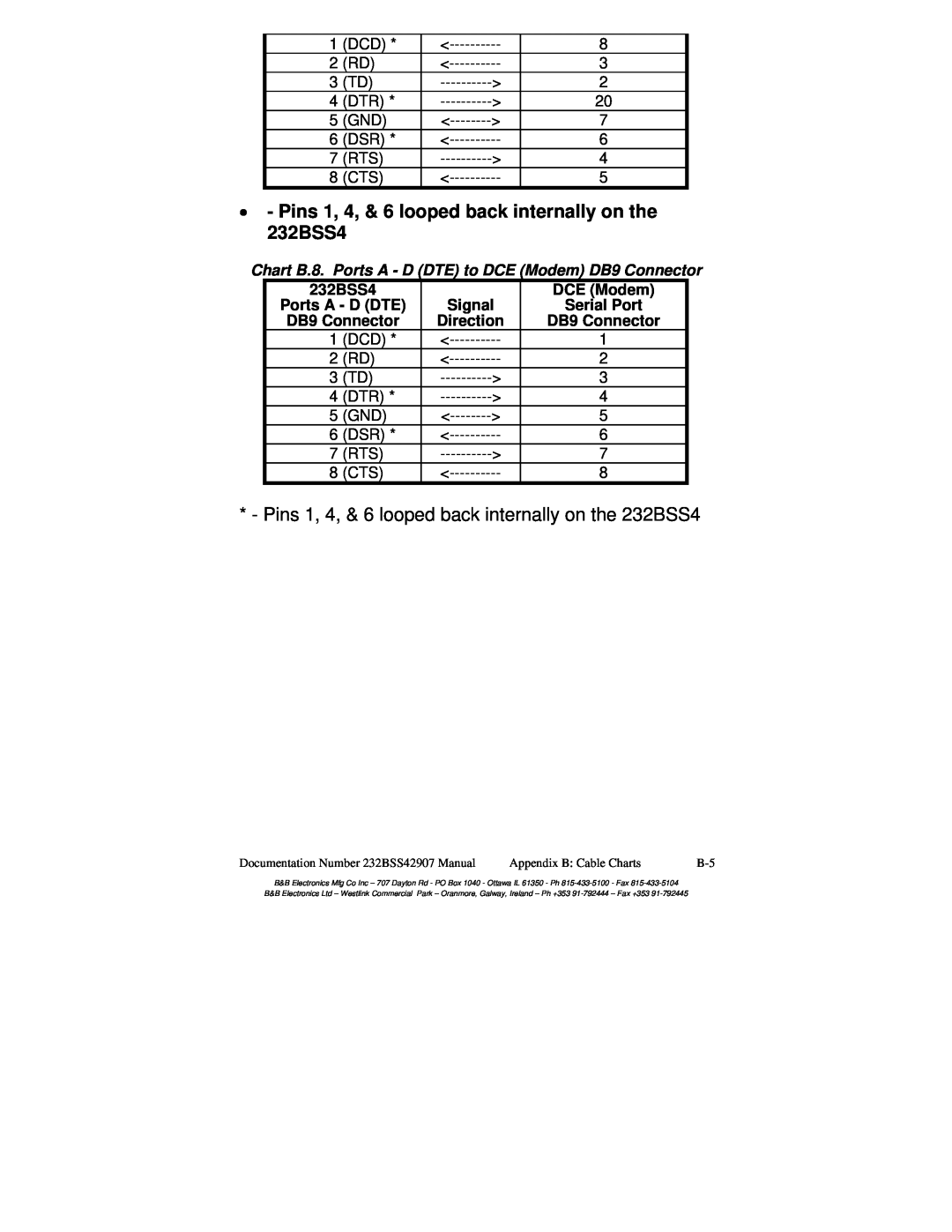
Pins 1, 4, & 6 looped back internally on the 232BSS4
Chart B.6. Ports A - D DTE to DTE PC DB9 Connector
Chart B.7. Ports A - D DTE to DCE Modem DB25 Connector
Chart B.8. Ports A - D DTE to DCE Modem DB9 Connector
Pins 1, 4, & 6 looped back internally on the 232BSS4
Documentation Number 232BSS42907 Manual
MASTER
Appendix C Block Diagram
UART
UART UART
Documentation Number 232BSS42907 Manual
DECLARATION OF CONFORMITY
Appendix D Declaration of Conformity