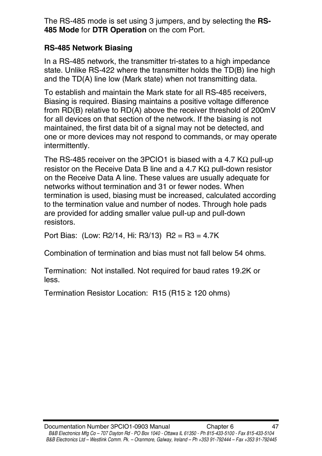
RS-422 specifications
B&B Electronics is renowned for its reliable and efficient solutions for industrial communication, and their Multi-Interface Ethernet Serial Servers stand out as versatile tools for connecting legacy serial devices to modern Ethernet networks. The compatibility with various serial communication protocols, including RS-485, RS-232, and RS-422, makes these servers indispensable in numerous applications that require reliable data transfer.One of the main features of B&B Electronics Multi-Interface Serial Servers is their ability to support multiple serial communication standards. This flexibility allows businesses to integrate older equipment with newer technologies seamlessly. The servers can act as a bridge, ensuring that data from RS-232 devices can be transmitted over Ethernet networks without modification.
These servers also boast a robust design that is built for industrial environments. With an operating temperature range suitable for harsh conditions, they ensure uninterrupted service in settings such as factories or outdoor installations. The metal housing of the devices provides durability and protection from physical damage, ensuring long-lasting performance.
In terms of connectivity, B&B Electronics Multi-Interface Serial Servers come with numerous options to accommodate different network configurations. They support various IP addressing schemes, allowing for easy integration into existing network infrastructures. Their Ethernet compatibility means they can handle high-volume data traffic, making them ideal for applications that demand high-speed communication.
Another significant feature is their user-friendly configuration options. The servers can be configured via a web interface, providing an intuitive and straightforward approach for users to set up and manage their devices remotely. This feature is especially beneficial for businesses with distributed operations, as it allows for easy monitoring and management from a central location.
The serial servers also incorporate advanced technologies such as TCP/IP and UDP protocols, enhancing data transmission reliability. This ensures that even in instances of network interruptions, data is not lost, thus maintaining the integrity of information being communicated between devices.
In summary, B&B Electronics Multi-Interface Ethernet Serial Servers serve as a crucial link between legacy serial devices and modern Ethernet networks. Their flexibility, robust design, and user-friendly features make them a preferred solution for industries looking to improve their communications infrastructure and streamline their operations. With the integration of cutting-edge technologies, these servers not only meet the current demands but also adapt to future advancements in network communications.
