Chapter 3 – Configuration & Programming
Configuration/Monitoring Software System Map
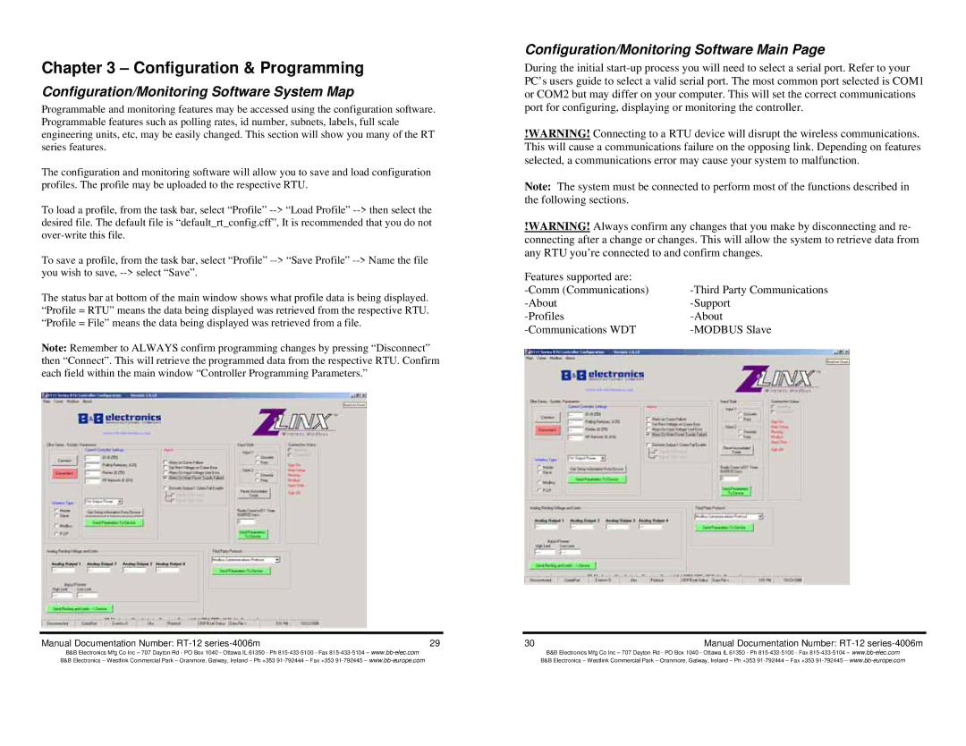
Programmable and monitoring features may be accessed using the configuration software. Programmable features such as polling rates, id number, subnets, labels, full scale engineering units, etc, may be easily changed. This section will show you many of the RT series features.
The configuration and monitoring software will allow you to save and load configuration profiles. The profile may be uploaded to the respective RTU.
To load a profile, from the task bar, select “Profile”
To save a profile, from the task bar, select “Profile”
The status bar at bottom of the main window shows what profile data is being displayed. “Profile = RTU” means the data being displayed was retrieved from the respective RTU. “Profile = File” means the data being displayed was retrieved from a file.
Note: Remember to ALWAYS confirm programming changes by pressing “Disconnect” then “Connect”. This will retrieve the programmed data from the respective RTU. Confirm each field within the main window “Controller Programming Parameters.”
Configuration/Monitoring Software Main Page
During the initial
!WARNING! Connecting to a RTU device will disrupt the wireless communications. This will cause a communications failure on the opposing link. Depending on features selected, a communications error may cause your system to malfunction.
Note: The system must be connected to perform most of the functions described in the following sections.
!WARNING! Always confirm any changes that you make by disconnecting and re- connecting after a change or changes. This will allow the system to retrieve data from any RTU you’re connected to and confirm changes.
Features supported are: |
|
|
|
| |
|
|
Manual Documentation Number: | 29 | 30 | Manual Documentation Number: |
B&B Electronics Mfg Co Inc – 707 Dayton Rd - PO Box 1040 - Ottawa IL 61350 - Ph
B&B Electronics Mfg Co Inc – 707 Dayton Rd - PO Box 1040 - Ottawa IL 61350 - Ph