RTU Alarms
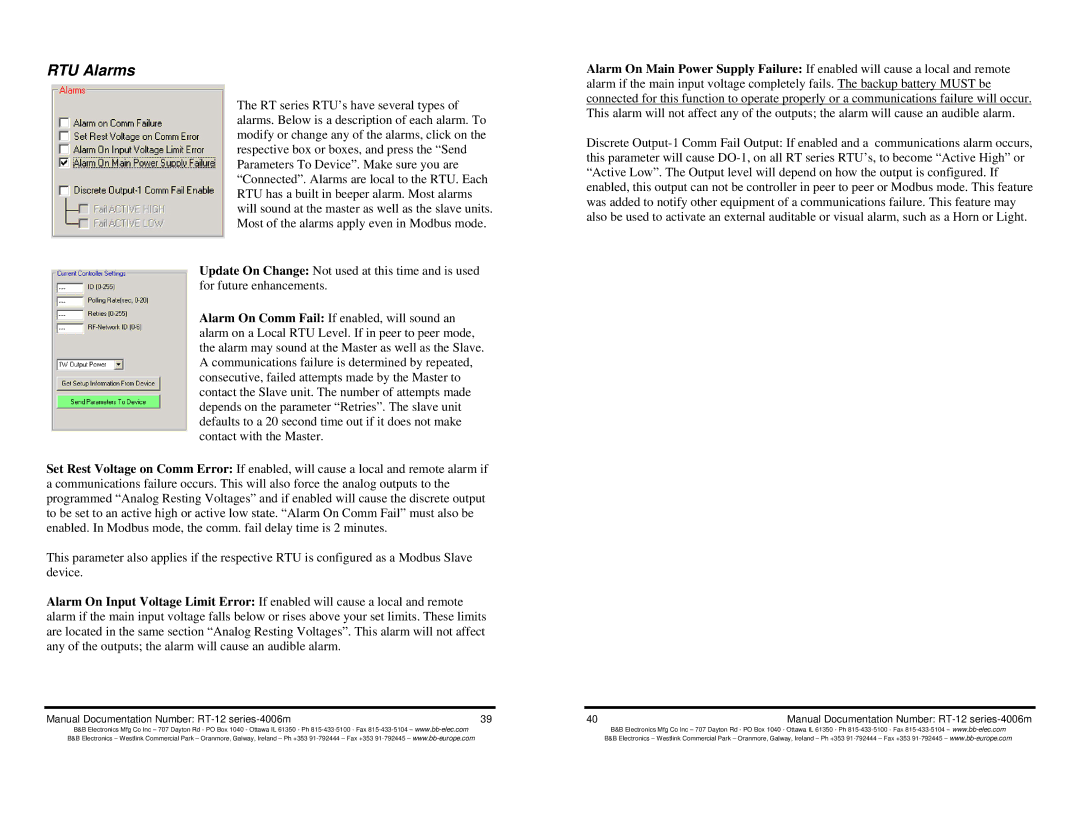
The RT series RTU’s have several types of alarms. Below is a description of each alarm. To modify or change any of the alarms, click on the respective box or boxes, and press the “Send Parameters To Device”. Make sure you are “Connected”. Alarms are local to the RTU. Each RTU has a built in beeper alarm. Most alarms will sound at the master as well as the slave units. Most of the alarms apply even in Modbus mode.
Update On Change: Not used at this time and is used for future enhancements.
Alarm On Comm Fail: If enabled, will sound an alarm on a Local RTU Level. If in peer to peer mode, the alarm may sound at the Master as well as the Slave. A communications failure is determined by repeated, consecutive, failed attempts made by the Master to contact the Slave unit. The number of attempts made depends on the parameter “Retries”. The slave unit defaults to a 20 second time out if it does not make contact with the Master.
Set Rest Voltage on Comm Error: If enabled, will cause a local and remote alarm if a communications failure occurs. This will also force the analog outputs to the programmed “Analog Resting Voltages” and if enabled will cause the discrete output to be set to an active high or active low state. “Alarm On Comm Fail” must also be enabled. In Modbus mode, the comm. fail delay time is 2 minutes.
This parameter also applies if the respective RTU is configured as a Modbus Slave device.
Alarm On Input Voltage Limit Error: If enabled will cause a local and remote alarm if the main input voltage falls below or rises above your set limits. These limits are located in the same section “Analog Resting Voltages”. This alarm will not affect any of the outputs; the alarm will cause an audible alarm.
Manual Documentation Number: | 39 |
B&B Electronics Mfg Co Inc – 707 Dayton Rd - PO Box 1040 - Ottawa IL 61350 - Ph
Alarm On Main Power Supply Failure: If enabled will cause a local and remote alarm if the main input voltage completely fails. The backup battery MUST be connected for this function to operate properly or a communications failure will occur. This alarm will not affect any of the outputs; the alarm will cause an audible alarm.
Discrete
40 | Manual Documentation Number: |
B&B Electronics Mfg Co Inc – 707 Dayton Rd - PO Box 1040 - Ottawa IL 61350 - Ph