8 | CONTROL TRIGGERS |
A control (trigger) system is provided on the Reference 200.1 S2 or Reference 200.2 S2 amplifiers to allow remote switching of the amplifier's standby on/off feature. The control input is designed to operate with a source (trigger) of
In addition, your amplifier has a control output circuit to allow control of an external device such as another power amplifier, projection screen, power strip, etc. The control output has the capability to source
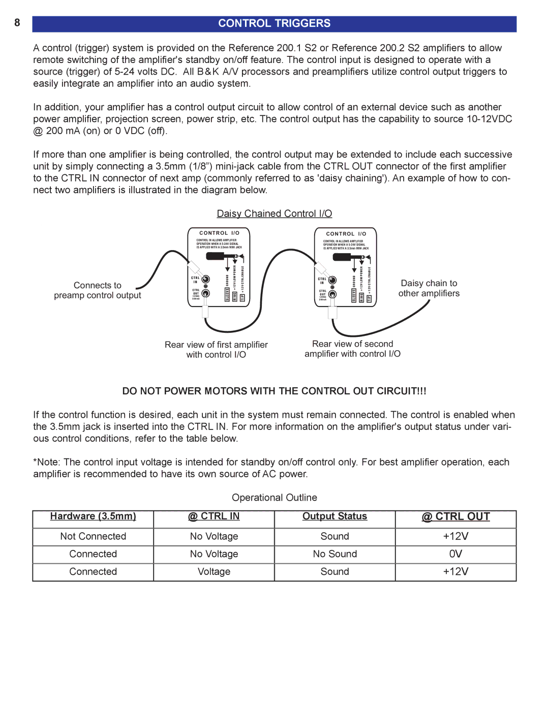
If more than one amplifier is being controlled, the control output may be extended to include each successive unit by simply connecting a 3.5mm (1/8”)
Daisy Chained Control I/O
C O N T R O L I / O | C O N T R O L I / O |
Connects to
preamp control output
CONTROL IN ALLOWS AMPLIFIER OPERATION WHEN A
|
|
|
|
|
|
|
|
|
|
|
|
|
|
|
| WER |
| ||
|
|
|
|
|
| BLE | |||
|
|
|
| NUOD | |||||
C T R L |
|
|
| WLOPO | LRTENA | ||||
I N |
|
| R | V | C | ||||
|
|
|
| G |
| +12 |
| 12V | |
C T R L |
|
| E |
| |||||
|
| EV |
|
|
|
| + | ||
O U T |
|
|
| G |
| ||||
1 2 V D C |
|
| EL |
| NI |
| PI | ||
2 0 0 m A |
|
| S |
| R |
| T | ||
|
|
|
|
|
|
|
|
|
|
|
|
|
|
|
|
|
|
|
|
CONTROL IN ALLOWS AMPLIFIER OPERATION WHEN A
|
|
|
|
|
|
|
|
|
|
|
|
|
|
|
|
|
|
|
| WER |
| ||
|
|
|
|
|
|
|
| BLE | |||
|
|
|
|
|
| NUOD | |||||
C T R L |
|
|
|
| WLOPO | LRTENA | |||||
I N |
|
|
| R | V | C | |||||
|
|
|
|
|
| G |
| +12 |
| 12V | |
C T R L |
|
|
| E |
| ||||||
|
|
| EV |
|
|
|
| + | |||
O U T |
|
|
|
| G |
| |||||
1 2 V D C |
|
|
| EL |
| NI |
| PI | |||
2 0 0 m A |
|
|
| S |
| R |
| T | |||
|
|
|
|
|
|
|
|
|
|
|
|
|
|
|
|
|
|
|
|
|
|
|
|
Daisy chain to other amplifiers
Rear view of first amplifier
with control I/O
Rear view of second
amplifier with control I/O
DO NOT POWER MOTORS WITH THE CONTROL OUT CIRCUIT!!!
If the control function is desired, each unit in the system must remain connected. The control is enabled when the 3.5mm jack is inserted into the CTRL IN. For more information on the amplifier's output status under vari- ous control conditions, refer to the table below.
*Note: The control input voltage is intended for standby on/off control only. For best amplifier operation, each amplifier is recommended to have its own source of AC power.
| Operational Outline |
| |
|
|
|
|
Hardware (3.5mm) | @ CTRL IN | Output Status | @ CTRL OUT |
|
|
|
|
Not Connected | No Voltage | Sound | +12V |
|
|
|
|
Connected | No Voltage | No Sound | 0V |
|
|
|
|
Connected | Voltage | Sound | +12V |
|
|
|
|