WIRING DIAGRAM
12
6
B | 5 | B |
B | 7 | B |
| ||
| Heat | |
|
|
|
|
|
|
|
|
| 120V, 60Hz, 1 Ph | ||||||
|
|
|
|
|
|
|
| Power Cord | |||||
|
|
|
|
|
|
|
|
|
|
| |||
|
|
|
|
|
|
|
| A |
| Green | |||
|
|
|
|
|
|
|
|
|
| Black | |||
|
|
|
|
|
|
|
|
|
| ||||
4 |
|
| N |
|
| ||||||||
|
|
|
|
|
|
|
|
|
|
|
|
| |
|
|
|
|
|
|
| White |
| A | ||||
|
|
|
|
|
|
|
|
|
|
|
|
| |
|
|
|
|
|
|
|
|
|
|
|
|
|
|
|
|
|
|
|
|
|
|
|
| A |
|
|
|
|
|
|
|
|
|
|
|
|
|
|
|
| |
|
|
|
|
|
| ||||||||
|
|
|
|
|
| ||||||||
|
|
|
|
|
|
|
|
|
|
|
|
|
|
B
2
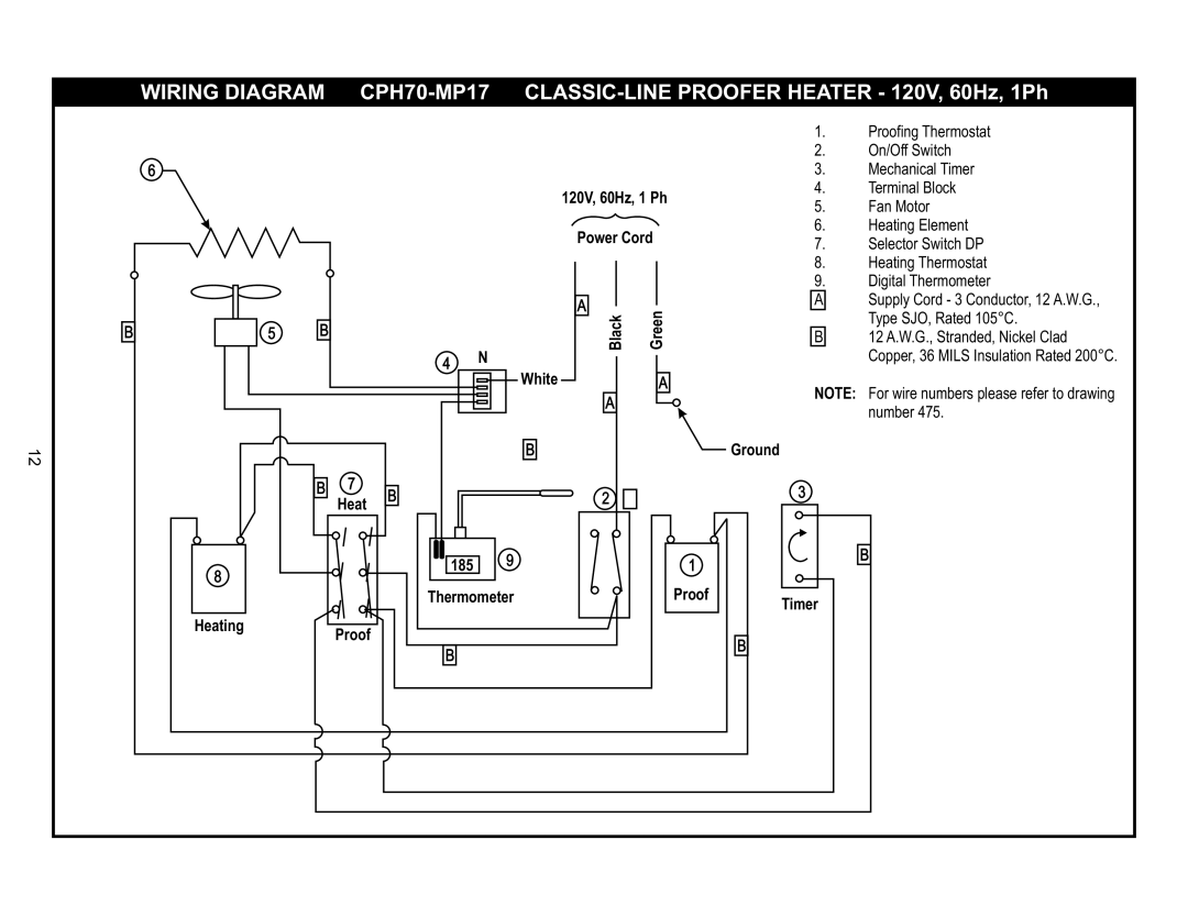
1.Proofing Thermostat
2.On/Off Switch
3.Mechanical Timer
4.Terminal Block
5.Fan Motor
6.Heating Element
7.Selector Switch DP
8.Heating Thermostat
9.Digital Thermometer
ASupply Cord - 3 Conductor, 12 A.W.G., Type SJO, Rated 105°C.
B12 A.W.G., Stranded, Nickel Clad Copper, 36 MILS Insulation Rated 200°C.
NOTE: For wire numbers please refer to drawing number 475.
Ground
3
8
HeatingProof
185 | 9 | 1 |
| ||
Thermometer | Proof | |
B
B
B
Timer
