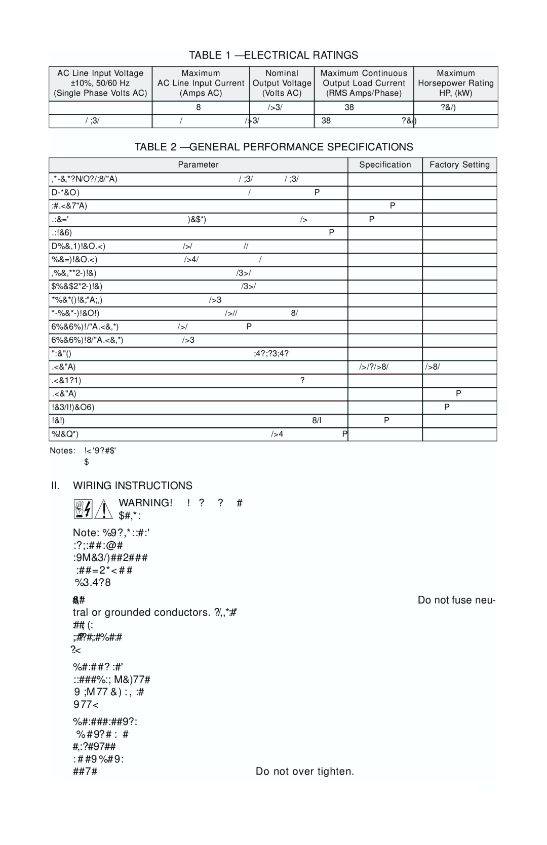
MN781W specifications
The Baldor MN781W is a versatile and robust motor designed for various industrial applications. Known for its high performance and efficiency, this motor is an integral component in diverse sectors, including manufacturing, agriculture, and energy production. Its design emphasizes durability, reliability, and energy efficiency, making it a preferred choice for many professionals.One of the main features of the Baldor MN781W is its premium efficiency rating, which ensures reduced energy consumption and lower operational costs. This motor meets or exceeds the efficiency standards set by the National Electrical Manufacturers Association (NEMA), contributing to substantial energy savings over its lifespan. When compared to traditional motors, the MN781W not only helps in cutting energy expenses but also supports environmentally friendly initiatives by minimizing carbon footprints.
The MN781W motor utilizes advanced insulation materials and coating technologies, providing enhanced protection against moisture, dust, and other environmental factors. This ensures optimal performance in challenging conditions while prolonging the motor’s life. The unique design of the motor housing and internal components minimizes heat generation, which is essential for extending operational longevity and preventing breakdowns.
In terms of technological features, the MN781W incorporates state-of-the-art bearing designs that reduce friction and enhance overall efficiency. This enables the motor to operate smoothly under heavy loads, which is particularly beneficial in industrial applications requiring consistent performance. Additionally, the motor is equipped with built-in thermal protection, which automatically shuts down the motor in case of overheating, thereby preventing damage and ensuring safety.
Another significant characteristic of the Baldor MN781W is its ease of installation and maintenance. The motor is designed with user-friendly access points for wiring and inspection, allowing technicians to conduct routine checks and repairs with minimal downtime. Furthermore, its modular design supports a range of mounting options, enabling seamless integration into existing systems.
In conclusion, the Baldor MN781W stands out as a reliable, energy-efficient motor that meets the demands of modern industries. With its premium efficiency rating, advanced protection features, and easy maintenance, it is an excellent choice for any business looking to enhance operational efficiency and reduce costs. Whether used in heavy machinery or process equipment, the MN781W ensures optimal performance and reliability, making it a valuable investment in industrial applications.

