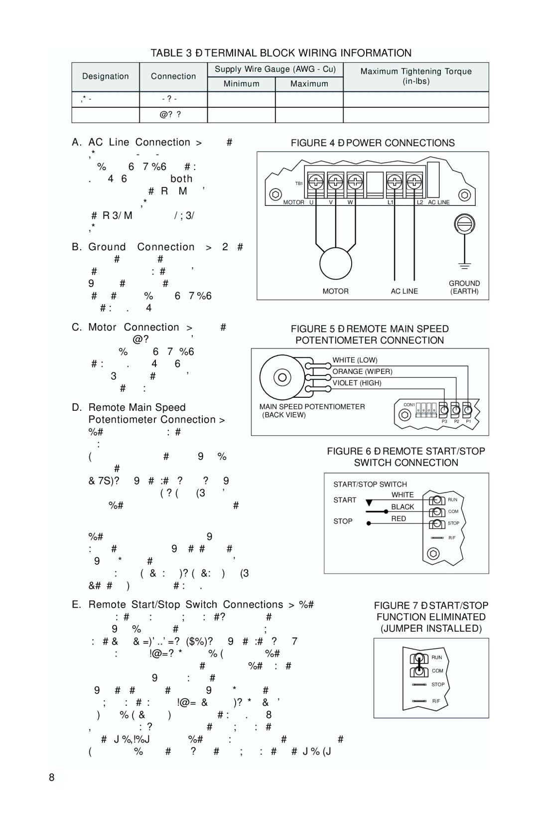
Baldor MN781W manual Terminal Block Wiring Information, Power Connections

Models: MN781W

1 16
Download 16 pages 56.25 Kb
Page 8
Image 8
FIGURE 7 – START/STOP FUNCTION ELIMINATED (JUMPER INSTALLED)
RUN
COM
STOP
R/F

TABLE 3 – TERMINAL BLOCK WIRING INFORMATION

Designation

Connection

Supply Wire Gauge (AWG - Cu)

Maximum Tightening Torque

Minimum

Maximum

(in-lbs)


AC Line Input

L1, L2

22

12

12


Motor

U, V, W

22

12

12


A. AC Line Connection – Wire the AC line input to L1 and L2 terminals of Terminal Block TB1 as shown in Figure 4. Be sure both Jumpers J1 and J2 are set to the “115V” posi- tion for 115 Volt AC line input or to the “230V” position for 208/230 Volt AC line input.

B. Ground Connection – Earth ground the control chassis using the green ground screw that is pro- vided on the inside of the control to the right side of Terminal Block TB1 as shown in Figure 4.

FIGURE 4 – POWER CONNECTIONS

TB1


MOTOR

U

V

W

L1

L2

AC LINE


MOTOR

AC LINE

GROUND


(EARTH)

C. Motor Connection – Wire the

FIGURE 5 – REMOTE MAIN SPEED

motor leads to U, V and W termi-

POTENTIOMETER CONNECTION

nals of

Terminal

Block

TB1 as


WHITE (LOW)


shown

in Figure

4.

Be sure


ORANGE (WIPER)

Jumper J3 is set to the correspon-


VIOLET (HIGH)


ding motor horsepower rating.


D. Remote Main Speed


MAIN SPEED POTENTIOMETER

CON1


Potentiometer Connection –

(BACK VIEW)


P3 P2 P1

The control is supplied with a


prewired Main Speed


FIGURE 6 – REMOTE START/STOP

Potentiometer mounted on the front cover. To

SWITCH CONNECTION

operate the control from a remote potentiometer


(5kΩ), remove the white, orange, and violet

START/STOP SWITCH

potentiometer leads from P1, P2 and P3 termi-

START

WHITE

nals. The leads may be taped and left inside the

RUN


BLACK

control.


COM


STOP

RED


STOP

The potentiometer assembly may be removed if a


R/F

watertight seal is used to cover the hole in the front


cover. Connect the remote main speed poten-


tiometer wires to P1 (low side), P2 (wiper) and P3


(high side) terminals as shown in Figure 5.


E. Remote Start/Stop Switch Connections – The control is supplied with a prewired Start/Stop switch, mounted on the front cover. To operate the control from a remote Start/Stop Switch (type (ON)-OFF-ON, SPDT), remove the white, black and red wires from RUN, COM and STOP terminals. The leads may be taped and left in the control. The switch assembly may be removed if a watertight seal is used to cover the hole in the front cover. Connect the remote Start/Stop Switch wires to RUN (momentary), COM (com- mon) and STOP (constant) terminals as shown in Figure 6. After applying power, momentarily set the Start/Stop Switch

to the "START" position. The motor will operate at the set speed of the Main Speed Potentiometer. To stop the motor, set the Start/Stop Switch to the "STOP" position.

6

Page 8
Image 8
Baldor MN781W manual Terminal Block Wiring Information, Power Connections

MN781W specifications

The Baldor MN781W is a versatile and robust motor designed for various industrial applications. Known for its high performance and efficiency, this motor is an integral component in diverse sectors, including manufacturing, agriculture, and energy production. Its design emphasizes durability, reliability, and energy efficiency, making it a preferred choice for many professionals.

One of the main features of the Baldor MN781W is its premium efficiency rating, which ensures reduced energy consumption and lower operational costs. This motor meets or exceeds the efficiency standards set by the National Electrical Manufacturers Association (NEMA), contributing to substantial energy savings over its lifespan. When compared to traditional motors, the MN781W not only helps in cutting energy expenses but also supports environmentally friendly initiatives by minimizing carbon footprints.

The MN781W motor utilizes advanced insulation materials and coating technologies, providing enhanced protection against moisture, dust, and other environmental factors. This ensures optimal performance in challenging conditions while prolonging the motor’s life. The unique design of the motor housing and internal components minimizes heat generation, which is essential for extending operational longevity and preventing breakdowns.

In terms of technological features, the MN781W incorporates state-of-the-art bearing designs that reduce friction and enhance overall efficiency. This enables the motor to operate smoothly under heavy loads, which is particularly beneficial in industrial applications requiring consistent performance. Additionally, the motor is equipped with built-in thermal protection, which automatically shuts down the motor in case of overheating, thereby preventing damage and ensuring safety.

Another significant characteristic of the Baldor MN781W is its ease of installation and maintenance. The motor is designed with user-friendly access points for wiring and inspection, allowing technicians to conduct routine checks and repairs with minimal downtime. Furthermore, its modular design supports a range of mounting options, enabling seamless integration into existing systems.

In conclusion, the Baldor MN781W stands out as a reliable, energy-efficient motor that meets the demands of modern industries. With its premium efficiency rating, advanced protection features, and easy maintenance, it is an excellent choice for any business looking to enhance operational efficiency and reduce costs. Whether used in heavy machinery or process equipment, the MN781W ensures optimal performance and reliability, making it a valuable investment in industrial applications.