|
|
|
| Barco, Inc. | Toll Free: | +1 (888) | |
|
|
|
| 11101 | Trade Center Drive | Fax: | +1 (916) |
|
|
|
| ||||
| QUICK START GUIDE | Rancho Cordova, CA | Technical Support: | +1 (866) | |||
Visibly yours | 95670 | • USA | Website: | www.barco.com | |||
|
|
|
| ||||
|
|
|
|
|
|
|
|
|
|
|
|
|
|
|
|
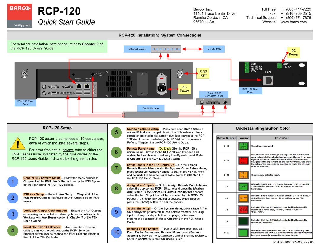
RCP-120 Installation: System Connections
For detailed installation instructions, refer to Chapter 2 of the
Ethernet Switch
To
DC
![]() Power
Power
Panel
12V DC OUT
1.5A
Ethernet | Ethernet |
Port 1 | Port 2 |
| Cable Harness |
AC
Power
Script
Light
Touch ScreenPanel
Connector Panel
| USB | 12V DC | |
|
|
|
|
|
|
|
|
|
|
|
|
RCP-120 Setup
For
General FSN System Setup — Follow the steps outlined in
1Chapter 6 of the FSN User’s Guide to setup the FSN System before connecting the
FSN Aux Setup — Refer to Aux Setup in Chapter 6 of the
2FSN User’s Guide to configure the Aux Outputs on the FSN system.
Verify Aux Output Configuration — Ensure the Aux Outputs
3are working as expected by following the steps outlined in the Working with Aux Buses section in Chapter 7 of the FSN User’s Guide.
Install the
4cable to connect the LAN port on the
5
6
7
8
9
10
Communications Setup — Make sure each
Remote Panel Name — (Optional) Give the
Setup Panels in the FSN Controller — On the Assign Remote Panels Menu, under the System, Other Setup Menu, press {Discover Remote Panels} to search the FSN network and populate the Remote Panel Table. Refer to Chapter 4 in the
Assign Aux Outputs — On the Assign Remote Panels Menu, select the appropriate
Saving the Setup — On the System Menu, press {Save All} to save all system parameters to
Backing up the System — Insert a USB drive into the USB Port. On the Backup and Restore Menu, press {Backup System} to back up the system setup and all memory registers. Refer to Chapter 6 in the FSN User’s Guide.
Understanding Button Color
P/N