FRESH AIR INTAKE

This unit is equipped with a fresh air damper assembly. The damper blade is locked in the closed position when the unit is shipped from the Factory. To allow the damper to operate remove the two plastic locking pins, one on each end of the blade. This will allow for maximum fresh airflow. The damper blade will now open when the indoor blower is operating. If less than maximum fresh airflow is required, reinsert the plastic pins to limit damper blade opening to desired level. Two extra pins are provided (taped to the inside of the assembly) which may be used to hold the blade in some position other than minimum or maximum position. This fresh air assembly is located in the rear of the unit and to gain access to make these adjustments remove the air filter service door.

All capacity, efficiency and cost of operation information as required for Department of Energy “Energyguide” Fact Sheets are based upon the fresh air blank-off plate in place and is recommended for maximum energy efficiency.

The blank-off plate is available upon request from the factory and is installed in place of the fresh air damper shipped with each unit.

For details on energy recovery ventilation see separate section.

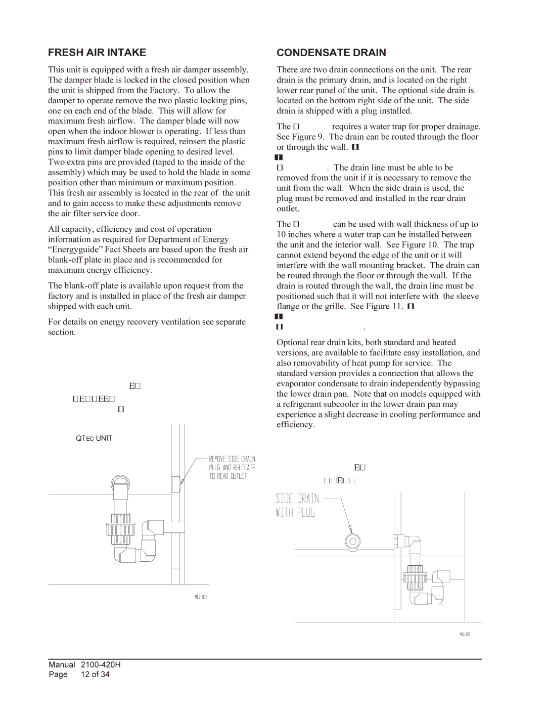
FIGURE 9

OPTIONAL SIDE DRAIN (SIDE VIEW)

INSTALLATION

QTEC UNIT

CONDENSATE DRAIN

There are two drain connections on the unit. The rear drain is the primary drain, and is located on the right lower rear panel of the unit. The optional side drain is located on the bottom right side of the unit. The side drain is shipped with a plug installed.

The side drain requires a water trap for proper drainage. See Figure 9. The drain can be routed through the floor or through the wall. If the drain is to be routed through an unconditioned space, it must be protected from freezing. The drain line must be able to be removed from the unit if it is necessary to remove the unit from the wall. When the side drain is used, the plug must be removed and installed in the rear drain outlet.

The rear drain can be used with wall thickness of up to 10 inches where a water trap can be installed between the unit and the interior wall. See Figure 10. The trap cannot extend beyond the edge of the unit or it will interfere with the wall mounting bracket. The drain can be routed through the floor or through the wall. If the drain is routed through the wall, the drain line must be positioned such that it will not interfere with the sleeve flange or the grille. See Figure 11. If the drain is to be routed through an unconditioned space, it must be protected from freezing.

Optional rear drain kits, both standard and heated versions, are available to facilitate easy installation, and also removability of heat pump for service. The standard version provides a connection that allows the evaporator condensate to drain independently bypassing the lower drain pan. Note that on models equipped with a refrigerant subcooler in the lower drain pan may experience a slight decrease in cooling performance and efficiency.

FIGURE 10

STANDARD REAR DRAIN

Manual

2100-420H

Page

12 of 34

Page 12
Image 12
Bard QH243, QH602 Fresh AIR Intake, Condensate Drain, Optional Side Drain Side View Installation, Standard Rear Drain

QH482, QH243, QH302, QH422, QH602 specifications

Bard has established itself as a leader in the heating, ventilation, and air conditioning (HVAC) industry with its innovative line of products, including the Bard QH series. Models such as QH362, QH602, QH422, QH302, and QH243 showcase the perfect blend of performance, efficiency, and advanced technology.

The Bard QH362 is built for both affordability and efficiency, making it ideal for smaller commercial spaces. This model offers a cooling capacity of 36,000 BTUs, providing optimal comfort with minimal energy consumption. Its robust design ensures long-lasting performance, while the air-cooled condenser enhances reliability in various climates.

The QH602 model takes it a step further with enhanced cooling capabilities, boasting a 60,000 BTU rating. This unit is particularly well-suited for larger commercial applications. Its advanced heat pump technology allows for efficient heating and cooling, ensuring indoor comfort year-round. The QH602 features a user-friendly control system that optimizes energy use and simplifies operation.

Next up, the QH422 model is designed for mid-sized commercial environments, offering 42,000 BTUs of cooling power. This model is distinguished by its energy-efficient design, significantly reducing operational costs while maintaining high-performance levels. The QH422 includes a smart thermostat that allows users to monitor and adjust settings remotely, further enhancing energy management.

The QH302 model is perfect for businesses looking for a balance between power and efficiency. With a capacity of 30,000 BTUs, this unit effectively meets the needs of medium-sized spaces. Its compact design allows for easy installation and maintenance, making it a favorite among commercial property managers.

Lastly, the QH243 model rounds out the series with a 24,000 BTU capacity, ideal for smaller commercial applications. This model showcases Bard's commitment to energy efficiency, equipped with environmentally friendly refrigerants and advanced insulation materials that minimize energy loss.

These Bard models feature innovative technologies such as variable-speed fans, which ensure consistent airflow regardless of outdoor conditions. Additionally, noise-reduction technologies provide a quieter operation, creating a more pleasant indoor environment.

In summary, the Bard QH series, including the QH362, QH602, QH422, QH302, and QH243, offers a comprehensive range of HVAC solutions tailored to diverse commercial needs. With their efficient designs, advanced technology, and focus on reliability, these models set the standard for modern heating and cooling equipment.