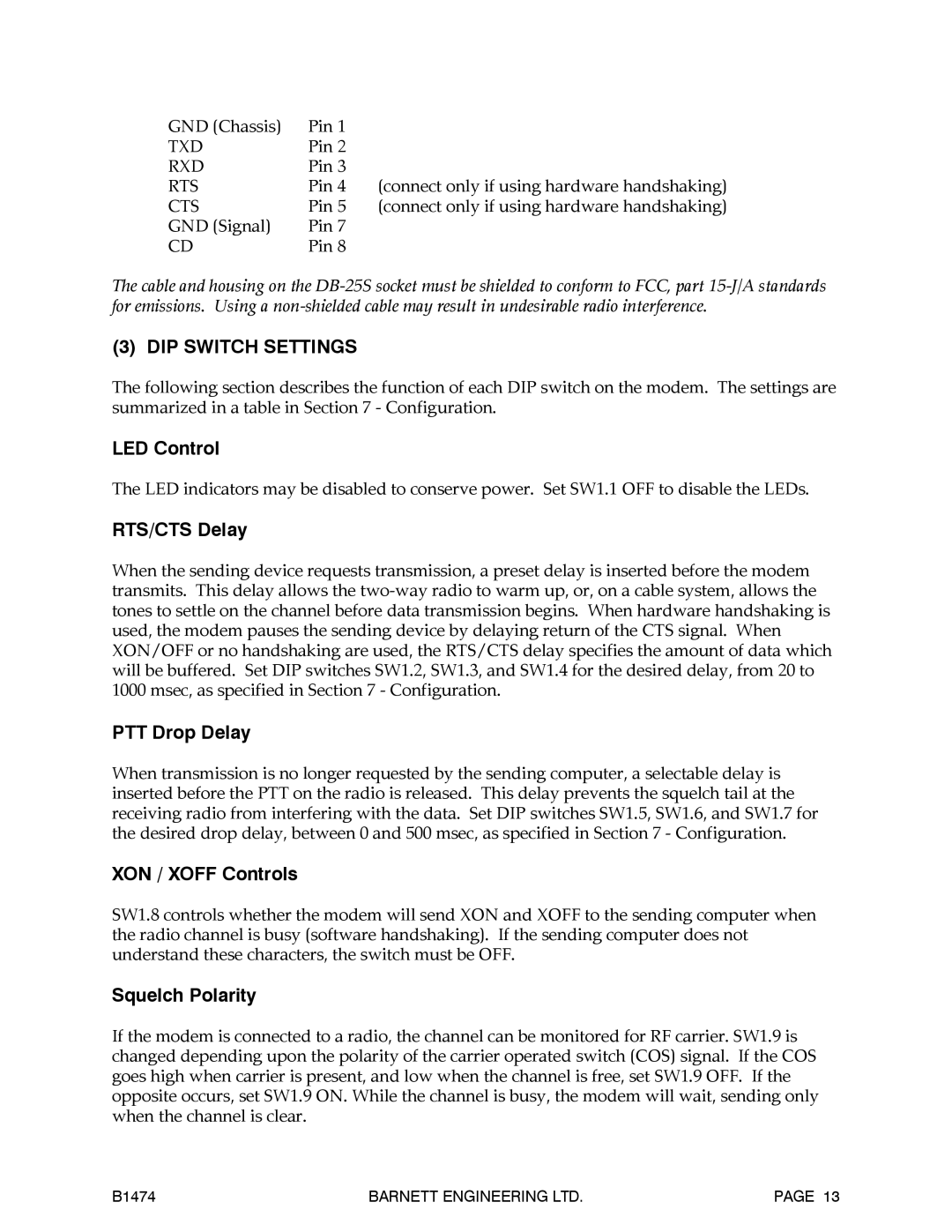
GND (Chassis) | Pin 1 |
|
TXD | Pin 2 |
|
RXD | Pin 3 | (connect only if using hardware handshaking) |
RTS | Pin 4 | |
CTS | Pin 5 | (connect only if using hardware handshaking) |
GND (Signal) | Pin 7 |
|
CD | Pin 8 |
|
The cable and housing on the
(3) DIP SWITCH SETTINGS
The following section describes the function of each DIP switch on the modem. The settings are summarized in a table in Section 7 - Configuration.
LED Control
The LED indicators may be disabled to conserve power. Set SW1.1 OFF to disable the LEDs.
RTS/CTS Delay
When the sending device requests transmission, a preset delay is inserted before the modem transmits. This delay allows the
PTT Drop Delay
When transmission is no longer requested by the sending computer, a selectable delay is inserted before the PTT on the radio is released. This delay prevents the squelch tail at the receiving radio from interfering with the data. Set DIP switches SW1.5, SW1.6, and SW1.7 for the desired drop delay, between 0 and 500 msec, as specified in Section 7 - Configuration.
XON / XOFF Controls
SW1.8 controls whether the modem will send XON and XOFF to the sending computer when the radio channel is busy (software handshaking). If the sending computer does not understand these characters, the switch must be OFF.
Squelch Polarity
If the modem is connected to a radio, the channel can be monitored for RF carrier. SW1.9 is changed depending upon the polarity of the carrier operated switch (COS) signal. If the COS goes high when carrier is present, and low when the channel is free, set SW1.9 OFF. If the opposite occurs, set SW1.9 ON. While the channel is busy, the modem will wait, sending only when the channel is clear.
B1474 | BARNETT ENGINEERING LTD. | PAGE 13 |
