|
| R.W. Beckett Corporation |
|
| |
|
| Mail: P.O. Box 1289, Elyria, OH 44036 ● Phone: |
|
| R.W. Beckett Canada Ltd. |
| PARTS & ACCESSORIES | Unit 3 - 430 Laird Road, Guelph, Ontario, Canada N1G 3X7 ● Phone: |
|
| www.beckettcorp.com |
|
|
|
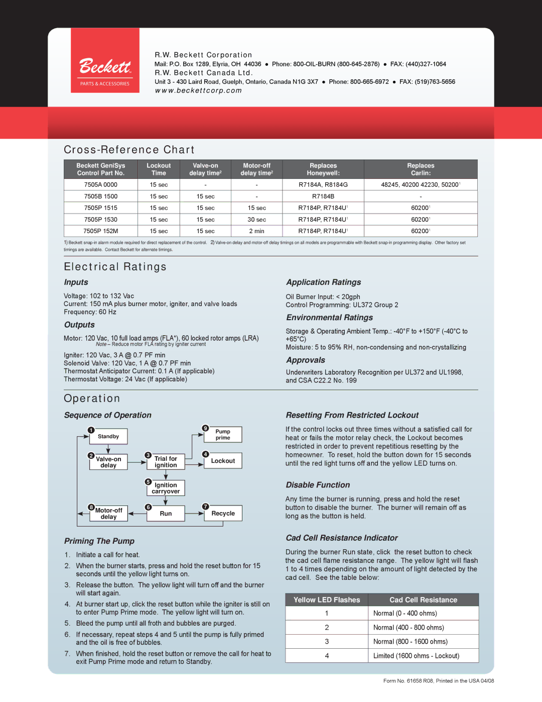
Cross-Reference Chart
Beckett GeniSys | Lockout | Replaces | Replaces | ||
Control Part No. | Time | delay time2 | delay time2 | Honeywell: | Carlin: |
|
|
|
|
|
|
7505A 0000 | 15 sec | - | - | R7184A, R8184G | 48245, 40200 42230, 502001 |
|
|
|
|
|
|
7505B 1500 | 15 sec | 15 sec | - | R7184B | - |
|
|
|
|
|
|
7505P 1515 | 15 sec | 15 sec | 15 sec | R7184P, R7184U1 | 602001 |
|
|
|
|
|
|
7505P 1530 | 15 sec | 15 sec | 30 sec | R7184P, R7184U1 | 602001 |
|
|
|
|
|
|
7505P 152M | 15 sec | 15 sec | 2 min | R7184P, R7184U1 | 602001 |
|
|
|
|
|
|
1)Beckett
Electrical Ratings
Inputs
Voltage: 102 to 132 Vac
Current: 150 mA plus burner motor, igniter, and valve loads
Frequency: 60 Hz
Outputs
Motor: 120 Vac, 10 full load amps (FLA*), 60 locked rotor amps (LRA)
Note – Reduce motor FLA rating by igniter current
Igniter: 120 Vac, 3 A @ 0.7 PF min
Solenoid Valve: 120 Vac, 1 A @ 0.7 PF min
Thermostat Anticipator Current: 0.1 A (If applicable)
Thermostat Voltage: 24 Vac (If applicable)
Application Ratings
Oil Burner Input: < 20gph
Control Programming: UL372 Group 2
Environmental Ratings
Storage & Operating Ambient Temp.:
Moisture: 5 to 95% RH,
Approvals
Underwriters Laboratory Recognition per UL372 and UL1998, and CSA C22.2 No. 199
Operation
Sequence of Operation
1 |
|
|
|
| 9 | Pump | |
Standby |
|
|
|
| |||
|
|
|
|
| prime | ||
2 |
|
|
| 3 Trial for | 4 |
| |
|
|
|
| ||||
| Lockout | ||||||
|
|
| |||||
| delay |
| ignition |
|
|
| |
|
|
|
|
| |||
5Ignition
carryover
8 | 6 | 7 | ||
delay |
| Run |
| Recycle |
|
| |||
|
|
|
| |
Resetting From Restricted Lockout
If the control locks out three times without a satisfied call for heat or fails the motor relay check, the Lockout becomes restricted in order to prevent repetitious resetting by the homeowner. To reset, hold the button down for 15 seconds until the red light turns off and the yellow LED turns on.
Disable Function
Any time the burner is running, press and hold the reset button to disable the burner. The burner will remain off as long as the button is held.
Priming The Pump
1.Initiate a call for heat.
2.When the burner starts, press and hold the reset button for 15 seconds until the yellow light turns on.
3.Release the button. The yellow light will turn off and the burner will start again.
4.At burner start up, click the reset button while the igniter is still on to enter Pump Prime mode. The yellow light will turn on.
5.Bleed the pump until all froth and bubbles are purged.
6.If necessary, repeat steps 4 and 5 until the pump is fully primed and the oil is free of bubbles.
7.When finished, hold the reset button or remove the call for heat to exit Pump Prime mode and return to Standby.
Cad Cell Resistance Indicator
During the burner Run state, click the reset button to check the cad cell flame resistance range. The yellow light will flash 1 to 4 times depending on the amount of light detected by the cad cell. See the table below:
Yellow LED Flashes | Cad Cell Resistance |
1Normal (0 - 400 ohms)
2Normal (400 - 800 ohms)
3Normal (800 - 1600 ohms)
4Limited (1600 ohms - Lockout)
Form No. 61658 R08, Printed in the USA 04/08
