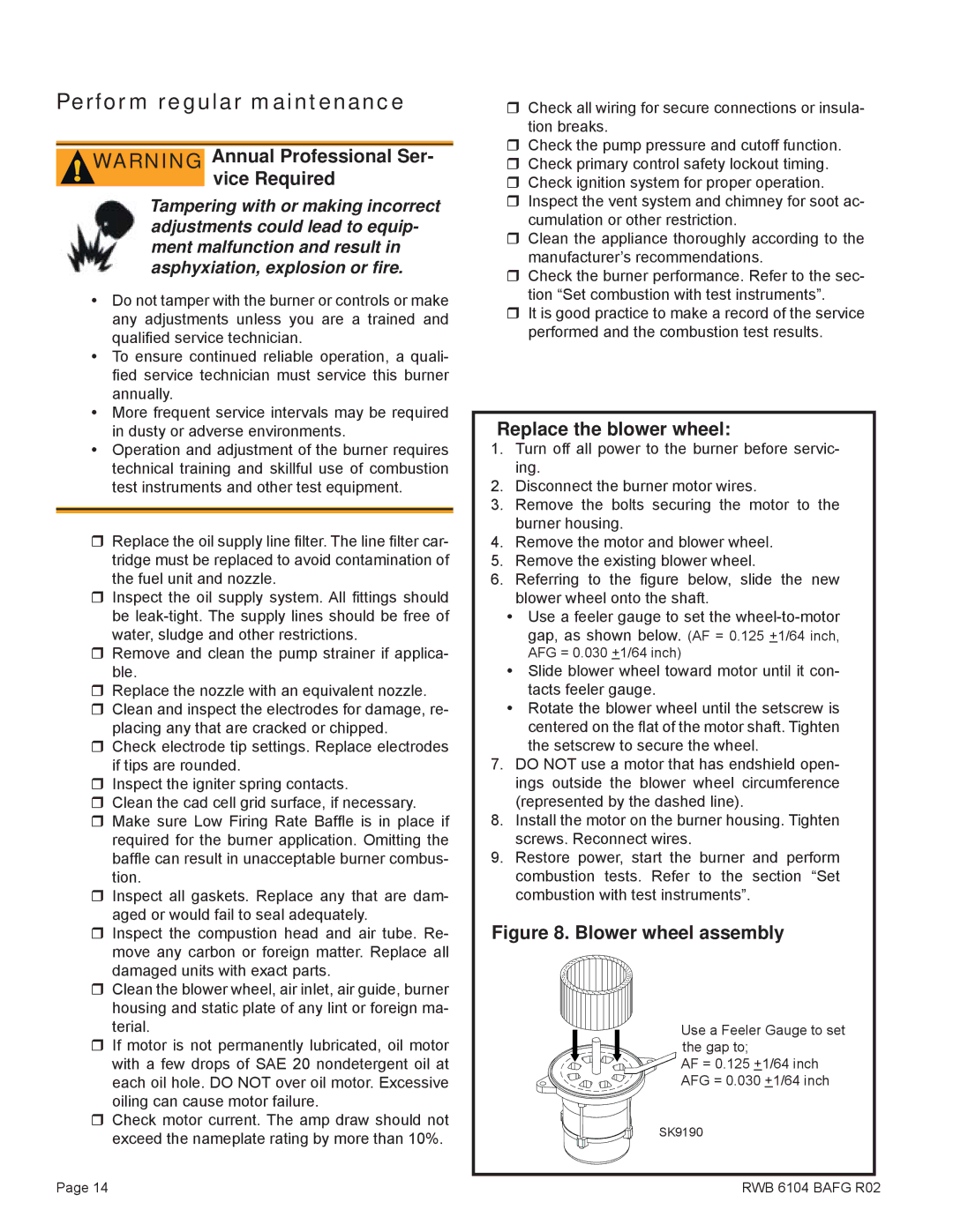
Oil Burner, AFG, AF specifications
Beckett AF and AFG oil burners are well-known for their reliability and efficiency in residential and commercial heating systems. These burners are engineered to optimize performance while minimizing maintenance needs, making them a preferred choice in the industry.One of the standout features of the Beckett AFG (Advanced Fuel Gas) burner is its advanced technology that allows for a more efficient combustion process. The AFG model boasts a unique air and fuel delivery system that enables precise control over the fuel-air mixture, resulting in improved efficiency and reduced emissions. This technology helps homeowners lower their energy bills while also supporting environmental sustainability.
The Beckett AF model also shares similar reliability features, focusing on consistent performance and ease of use. Both models come equipped with a durable metal housing that withstands the wear and tear of daily operation, ensuring longevity and decreased need for replacement over time. Their compact design also allows for easy installation and fits seamlessly into existing heating systems.
Moreover, the Beckett oil burners utilize a highly effective nozzle that atomizes the fuel perfectly, ensuring optimum combustion efficiency. The nozzle is designed for easy replacement, making maintenance a straightforward task for users. The burners also feature a reliable ignition system that provides quick and safe lighting, reducing the risk of operational hazards and improving user confidence.
Another characteristic of the Beckett AFG and AF models is their quiet operation. Designed with sound-dampening materials and innovative engineering, these burners operate quietly, making them suitable for residential environments where noise can be a concern.
Additionally, both models are designed for easy serviceability. Their modular construction allows technicians to access components quickly, which minimizes downtime during service calls. This is particularly beneficial for professionals who require efficiency in their servicing routines.
In summary, Beckett AF and AFG oil burners combine cutting-edge technology with durable construction and design features. Their efficiency, reliability, and user-friendly characteristics make them a top choice among those looking for effective heating solutions. With an emphasis on performance and ease of maintenance, Beckett continues to set the standard in the oil burner market.

