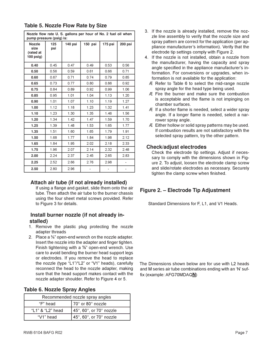
Table 5. Nozzle Flow Rate by Size

Nozzle flow rate U. S. gallons per hour of No. 2 fuel oil when pump pressure (psig) is:

Nozzle

125

140 psi

150 psi

175 psi

200 psi

size

psi


(rated at


100 psig)


0.40

0.45

0.47

0.49

0.53

0.56

0.50

0.56

0.59

0.61

0.66

0.71

0.60

0.67

0.71

0.74

0.79

0.85

0.65

0.73

0.77

0.80

0.86

0.92

0.75

0.84

0.89

0.92

0.99

1.06

0.85

0.95

1.01

1.04

1.13

1.20

0.90

1.01

1.07

1.10

1.19

1.27

1.00

1.12

1.18

1.23

1.32

1.41

1.10

1.23

1.30

1.35

1.46

1.56

1.20

1.34

1.42

1.47

1.59

1.70

1.25

1.39

1.48

1.53

1.65

1.77

1.35

1.51

1.60

1.65

1.79

1.91

1.50

1.68

1.77

1.84

1.98

2.12

1.65

1.84

1.95

2.02

2.18

2.33

1.75

1.96

2.07

2.14

2.32

2.48

2.00

2.24

2.37

2.45

2.65

2.83


2.25

2.52

2.66

2.76

2.98

-


2.50

2.80

2.96

-

-

-


3.If the nozzle is already installed, remove the noz- zle line assembly to verify that the nozzle size and spray pattern are correct for the application (per ap- pliance manufacturer’s information). Verify that the electrode tip settings comply with Figure 2.

4.If the nozzle is not installed, obtain a nozzle from the manufacturer, having the capacity and spray angle specified in the appliance manufacturer’s in- formation. For conversions or upgrades, when in- formation is not available for the application:

yRefer to Table 6 to select the mid-range nozzle spray angle for the head type being used.

yFire the burner and make sure the combustion is acceptable and the flame is not impinging on chamber surfaces.

yIf a shorter flame is needed, select a wider spray angle. If a longer flame is needed, select a nar- rower spray angle.

yEither hollow or solid spray patterns may be used. If combustion results are not satisfactory with the selected spray pattern, try the other pattern.

Check/adjust electrodes

Check the electrode tip settings. Adjust if neces- sary to comply with the dimensions shown in Fig- ure 2. To adjust, loosen the electrode clamp screw and slide/rotate electrodes as necessary. Securely tighten the clamp screw when finished.

Attach air tube (if not already installed)

If using a flange and gasket, slide them onto the air tube. Then attach the air tube to the burner chassis using the four sheet metal screws provided. Refer to Figure 3 for details.

Figure 2. – Electrode Tip Adjustment

Standard Dimensions for F, L1, and V1 Heads.

Install burner nozzle (if not already in- stalled)

1.Remove the plastic plug protecting the nozzle adapter threads

2.Place a ¾” open-end wrench on the nozzle adapter. Insert the nozzle into the adapter and finger tighten. Finish tightening with a ⅝” open-end wrench. Use care to avoid bending the burner head support legs or electrodes. If you remove the head to replace the nozzle (type “L1”/“L2” or “V1” heads), carefully reconnect the head to the nozzle adapter, making sure that the head support makes contact with the nozzle adapter shoulder. Refer to Figure 4 or 5.

Table 6. Nozzle Spray Angles

Recommended nozzle spray angles

“F” head

70° or 80° nozzle

“L1” & “L2” head

45°, 60°, or 70° nozzle

“V1” head

45°, 60°, or 70° nozzle

The Dimensions shown below are for use with L2 heads and M series air tube combinations ending with an ‘N’ suf- fix (example: AFG70MDAQN)

RWB 6104 BAFG R02

Page 7

Page 7
Image 7
Beckett Oil Burner, AFG manual Nozzle Flow Rate by Size, Check/adjust electrodes, Attach air tube if not already installed

Oil Burner, AFG, AF specifications

Beckett AF and AFG oil burners are well-known for their reliability and efficiency in residential and commercial heating systems. These burners are engineered to optimize performance while minimizing maintenance needs, making them a preferred choice in the industry.

One of the standout features of the Beckett AFG (Advanced Fuel Gas) burner is its advanced technology that allows for a more efficient combustion process. The AFG model boasts a unique air and fuel delivery system that enables precise control over the fuel-air mixture, resulting in improved efficiency and reduced emissions. This technology helps homeowners lower their energy bills while also supporting environmental sustainability.

The Beckett AF model also shares similar reliability features, focusing on consistent performance and ease of use. Both models come equipped with a durable metal housing that withstands the wear and tear of daily operation, ensuring longevity and decreased need for replacement over time. Their compact design also allows for easy installation and fits seamlessly into existing heating systems.

Moreover, the Beckett oil burners utilize a highly effective nozzle that atomizes the fuel perfectly, ensuring optimum combustion efficiency. The nozzle is designed for easy replacement, making maintenance a straightforward task for users. The burners also feature a reliable ignition system that provides quick and safe lighting, reducing the risk of operational hazards and improving user confidence.

Another characteristic of the Beckett AFG and AF models is their quiet operation. Designed with sound-dampening materials and innovative engineering, these burners operate quietly, making them suitable for residential environments where noise can be a concern.

Additionally, both models are designed for easy serviceability. Their modular construction allows technicians to access components quickly, which minimizes downtime during service calls. This is particularly beneficial for professionals who require efficiency in their servicing routines.

In summary, Beckett AF and AFG oil burners combine cutting-edge technology with durable construction and design features. Their efficiency, reliability, and user-friendly characteristics make them a top choice among those looking for effective heating solutions. With an emphasis on performance and ease of maintenance, Beckett continues to set the standard in the oil burner market.