‰Combustion air supply

yThe burner requires combustion air and ventilation air for reliable operation. Assure that the building and/or com- bustion air openings comply with National Fire Protec- tion Standard for Oil-Burning Equipment, NFPA 31. For appliance/burner units in confined spaces, the room must have an air opening near the top of the room plus one near the floor, each with a free area at least one square inch per 1,000 Btu/hr input of all fuel burning equipment in the room. For other conditions, refer to NFPA 31 (CSA B1139- M91 in Canada).

yIf there is a risk of the space being under negative pres- sure or of exhaust fans or other devices depleting available air for combustion and ventilation, the appliance/burner should be installed in an isolated room provided with out- side combustion air.

‰Clearances

yWith the burner installed in the appliance, there must be adequate space in front of and on the sides of the burner to allow access and operation. Verify that the clearance di- mensions comply with all local codes and with the appli- ance manufacturer’s recommendations.

‰Fuel supply

yThe fuel supply piping and tank must provide #1 or #2 fuel oil at pressure or vacuum conditions suitable for the fuel unit (oil pump) on the burner. Refer to fuel unit literature in the literature envelope in the burner carton to verify allow- able suction pressure.

Oil Supply Pressure Con- trol Required

Damage to the pump, filter or other compo- nent seals could cause possible oil leakage and potential fire hazard.

yThe oil supply inlet pressure to the fuel unit cannot ex- ceed 3 psig.

yDo NOT install valves in return line.

yEnsure that a pressure-limiting device is installed in ac- cordance with the latest edition of the NFPA 31.

If fuel supply is level with or higher than fuel unit

yWhen the fuel unit is not required to lift the oil, the instal- lation is usually suitable for either a one-pipe or two-pipe oil system. The oil pressure at the inlet of the fuel unit must not exceed 3 psig.

ySee Figure 8 for one-pipe fuel supply installations. See Figure 9 for two-pipe fuel supply installations.

If fuel supply is below the fuel unit —

yUse a two-pipe oil system when the fuel unit must lift the oil more than 8 feet if burner is equipped with a B fuel unit, or more than 2 feet if burner is equipped with an H fuel unit. The return line provided by the two-pipe system is needed to purge the air from the fuel lines and minimize the likelihood of air-related problems during operation.

‰Nozzle pressure

Correct Nozzle and Flow

Rate Required

Incorrect nozzles and flow rates could result in impaired combustion, under-firing, over-firing, sooting, puff-back of hot gases, smoke and potential fire or asphyxiation haz- ards.

Use only nozzles having the brand, flow rate (gph), spray angle and pattern specified by the appliance manufac- turer.

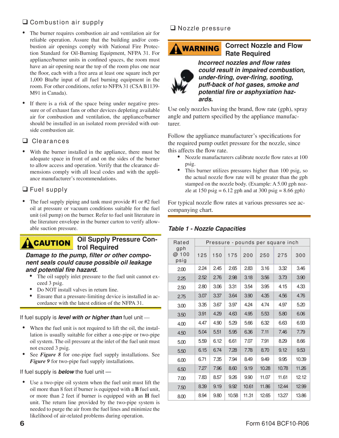
Follow the appliance manufacturer’s specifications for the required pump outlet pressure for the nozzle, since this affects the flow rate.

yNozzle manufacturers calibrate nozzle flow rates at 100 psig.

yThis burner utilizes pressures higher than 100 psig, so the actual nozzle flow rate will be greater than the gph stamped on the nozzle body. (Example: A 5.00 gph noz- zle at 150 psig = 6.12 gph and at 300 psig = 8.66 gph)

For typical nozzle flow rates at various pressures see ac- companying chart.

Table 1 - Nozzle Capacities

Rated

Pressure - pounds per square inch

gph


@ 100

125

150

175

200

250

275

300

psig


2.00

2.24

2.45

2.65

2.83

3.16

3.32

3.46

2.25

2.52

2.76

2.98

3.18

3.56

3.73

3.90

2.50

2.80

3.06

3.31

3.54

3.95

4.15

4.33

2.75

3.07

3.37

3.64

3.90

4.35

4.56

4.76

3.00

3.35

3.67

3.97

4.24

4.74

4.97

5.20

3.50

3.91

4.29

4.63

4.95

5.53

5.80

6.06

4.00

4.47

4.90

5.29

5.66

6.32

6.63

6.93

4.50

5.04

5.51

5.95

6.36

7.11

7.46

7.79

5.00

5.59

6.12

6.61

7.07

7.91

8.29

8.66

5.50

6.15

6.74

7.28

7.78

8.70

9.12

9.53

6.00

6.71

7.35

7.94

8.49

9.49

9.95

10.39

6.50

7.27

7.96

8.60

9.19

10.28

10.78

11.26

7.00

7.83

8.57

9.26

9.90

11.07

11.61

12.12

7.50

8.39

9.19

9.92

10.61

11.86

12.44

12.99

8.00

8.94

9.80

10.58

11.31

12.65

13.27

13.86

6

Form 6104 BCF10-R06

Page 6
Image 6
Beckett CF1000 manual Oil Supply Pressure Con- trol Required, Correct Nozzle and Flow Rate Required

CF1000 specifications

The Beckett CF1000 is a cutting-edge, reliable, and efficient commercial burner designed for use in various heating applications. Known for its exceptional performance, it is increasingly popular among businesses and contractors looking for an effective solution to meet their heating needs.

One of the main features of the CF1000 is its advanced combustion technology. The burner is engineered to deliver optimal combustion efficiency, reducing emissions and enhancing fuel economy. This technology not only helps in lowering operational costs but also aligns with modern environmental regulations, making the CF1000 a responsible choice for energy-conscious businesses.

Another notable characteristic of the CF1000 is its ability to handle multiple fuel types, including oil and natural gas. This versatility allows users to choose the best fuel source for their specific application, contributing to operational flexibility. Additionally, the CF1000 is equipped with a modulation system that adjusts the burner output in response to demand, ensuring consistent heating without unnecessary energy consumption.

The CF1000 also stands out for its compact design, making it easy to install in various settings, whether in commercial buildings or industrial facilities. Its robust construction is designed to withstand demanding conditions, ensuring longevity and reliability. Moreover, the burner comes with advanced safety features, including flame monitoring and integrated shut-off systems, helping to prevent potential hazards during operation.

Ease of maintenance is another significant advantage of the Beckett CF1000. The design incorporates user-friendly service access points, allowing technicians to perform routine maintenance and inspections quickly and efficiently. This not only ensures optimal performance but also extends the lifespan of the burner.

Furthermore, the CF1000 is supported by Beckett's extensive customer service and technical support. Their commitment to quality and satisfaction means that users can rely on expert assistance whenever needed, ensuring peace of mind.

Overall, the Beckett CF1000 is a premier choice for those seeking a high-performance commercial burner. With its advanced combustion technology, versatile fuel options, compact design, and a wealth of safety features, it delivers reliable heating solutions suitable for a wide range of applications. Its ease of maintenance combined with robust support services makes the CF1000 an intelligent investment for any business prioritizing efficiency, safety, and reliability in their heating systems.