Instruction Manual – Model CF2300A Oil Burner

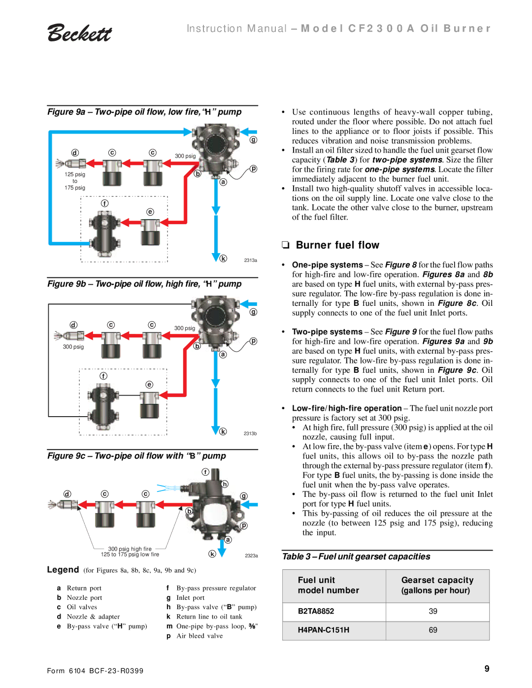
Figure 9a – Two-pipe oil flow, low fire,“H” pump

• Use continuous lengths of heavy-wall copper tubing,

routed under the floor where possible. Do not attach fuel

d

c

c

300 psig


125 psig


b

to


175 psig


f

e

g

p

a

lines to the appliance or to floor joists if possible. This

reduces vibration and noise transmission problems.

• Install an oil filter sized to handle the fuel unit gearset flow

capacity (Table 3) for two-pipe systems. Size the filter

for the firing rate for one-pipe systems. Locate the filter

immediately adjacent to the burner fuel unit.

• Install two high-quality shutoff valves in accessible loca-

tions on the oil supply line. Locate one valve close to the

tank. Locate the other valve close to the burner, upstream

of the fuel filter.

Burner fuel flow

k 2313a

Figure 9b – Two-pipe oil flow, high fire, “H” pump

One-pipe systems – See Figure 8 for the fuel flow paths

for high-fire and low-fire operation. Figures 8a and 8b

are based on type H fuel units, with external by-pass pres-

sure regulator. The low-fire by-pass regulation is done in-

d

c

c

300 psig


300 psig


b

f

e

g

p

a

ternally for type B fuel units, shown in Figure 8c. Oil

supply connects to one of the fuel unit Inlet ports.

Two-pipe systems – See Figure 9 for the fuel flow paths

for high-fire and low-fire operation. Figures 9a and 9b

are based on type H fuel units, with external by-pass pres-

sure regulator. The low-fire by-pass regulation is done in-

ternally for type B fuel units, shown in Figure 9c. Oil

supply connects to one of the fuel unit Inlet ports. Oil

return connects to the fuel unit Return port.

Low-fire/high-fire operation – The fuel unit nozzle port

pressure is factory set at 300 psig.

• At high fire, full pressure (300 psig) is applied at the oil

k 2313b

Figure 9c – Two-pipe oil flow with “B” pump

nozzle, causing full input.

• At low fire, the by-pass valve (item e) opens. For type H

fuel units, this allows oil to by-pass the nozzle path

through the external by-pass pressure regulator (item f).


f

d

c

c


b


300 psig high fire

k


125 to 175 psig low fire

h

g

p

a

2323a

For type B fuel units, the by-passing is done inside the

fuel unit when the by-pass valve operates.

• The by-pass oil flow is returned to the fuel unit Inlet

port for type H fuel units.

• This by-passing of oil reduces the oil pressure at the

nozzle (to between 125 psig and 175 psig), reducing

the input.

Table 3 – Fuel unit gearset capacities

Legend (for Figures 8a, 8b, 8c, 9a, 9b and 9c)

a

Return port

f

By-pass pressure regulator

b

Nozzle port

g

Inlet port

c

Oil valves

h

By-pass valve (“ B” pump)

d

Nozzle & adapter

k

Return line to oil tank

e By-pass valve (“ H” pump)

m

One-pipe by-pass loop, ³⁄₈"


p

Air bleed valve

Fuel unit

Gearset capacity

model number

(gallons per hour)


B2TA8852

39


H4PAN-C151H

69


Form 6104 BCF-23-R0399

9

Page 9
Image 9
Beckett CF 2300A Burner fuel flow, Fuel unit gearset capacities, Fuel unit Gearset capacity Model number Gallons per hour

CF 2300A specifications

The Beckett CF 2300A is a highly regarded oil burner designed for residential and light commercial use. Known for its reliability and efficient performance, the CF 2300A is a favored choice among HVAC professionals and homeowners alike. This model optimizes fuel efficiency while ensuring a consistent and dependable heat output, making it suitable for various heating applications.

One of the standout features of the Beckett CF 2300A is its advanced combustion technology. Equipped with a unique air-to-fuel ratio control system, this burner optimizes the mix of air and fuel, resulting in cleaner combustion and increased energy savings. This technology not only enhances heating efficiency but also reduces the environmental impact by minimizing harmful emissions.

The CF 2300A is designed with a sleek, compact profile that allows for easy installation in tight spaces. Its versatile mounting options and adjustable dimensions accommodate various installation configurations, making it a flexible choice for both new and retrofitting projects. Additionally, the burner is compatible with a wide range of fuel types, including traditional heating oil, which enhances its usability across different heating systems.

Built for durability, the Beckett CF 2300A features robust components that withstand the rigors of daily operation. Its heavy-duty construction ensures longevity, reducing the need for frequent replacements or repairs. Furthermore, it includes a reliable ignition system that provides quick starts and consistent operation, making it a dependable choice for homeowners.

Another key characteristic of the CF 2300A is its low noise operation. The design incorporates noise-reducing technologies that minimize the sound output during operation, contributing to a comfortable indoor environment. This feature is particularly beneficial in residential settings where quiet heating solutions are desired.

In conclusion, the Beckett CF 2300A oil burner combines innovative technologies with reliable performance characteristics. Its advanced combustion system, flexible installation options, robust construction, and quiet operation make it an optimal choice for residential and light commercial heating needs. With a focus on efficiency and longevity, the CF 2300A continues to set a standard in the industry, providing dependable heat while prioritizing environmental sustainability.