B300
1.3 Control elements
1
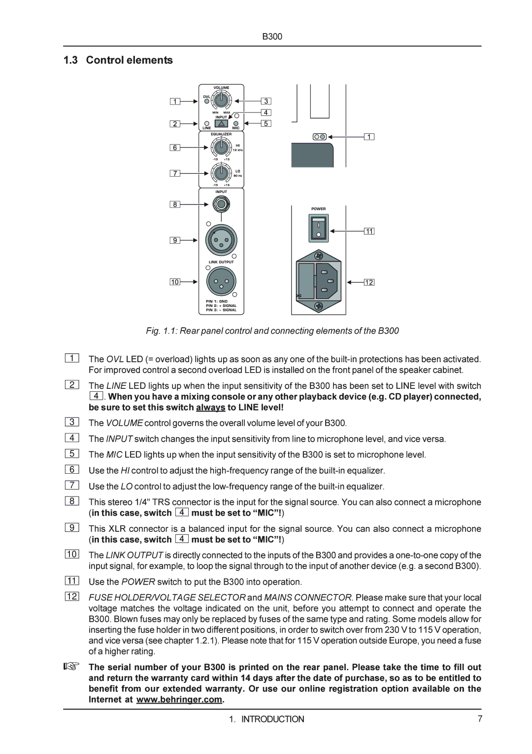
Fig. 1.1: Rear panel control and connecting elements of the B300
The OVL LED (= overload) lights up as soon as any one of the
2
3
4
5
6
7
8
9
10
The LINE LED lights up when the input sensitivity of the B300 has been set to LINE level with switch
![]() . When you have a mixing console or any other playback device (e.g. CD player) connected, be sure to set this switch always to LINE level!
. When you have a mixing console or any other playback device (e.g. CD player) connected, be sure to set this switch always to LINE level!
The VOLUME control governs the overall volume level of your B300.
The INPUT switch changes the input sensitivity from line to microphone level, and vice versa. The MIC LED lights up when the input sensitivity of the B300 is set to microphone level. Use the HI control to adjust the
Use the LO control to adjust the
This stereo 1/4" TRS connector is the input for the signal source. You can also connect a microphone (in this case, switch ![]() must be set to “MIC”!)
must be set to “MIC”!)
This XLR connector is a balanced input for the signal source. You can also connect a microphone (in this case, switch ![]()
![]()
![]() must be set to “MIC”!)
must be set to “MIC”!)
The LINK OUTPUT is directly connected to the inputs of the B300 and provides a
11
12
Use the POWER switch to put the B300 into operation.
FUSE HOLDER/VOLTAGE SELECTOR and MAINS CONNECTOR. Please make sure that your local voltage matches the voltage indicated on the unit, before you attempt to connect and operate the B300. Blown fuses may only be replaced by fuses of the same type and rating. Some models allow for inserting the fuse holder in two different positions, in order to switch over from 230 V to 115 V operation, and vice versa (see chapter 1.2.1). Please note that for 115 V operation outside Europe, you need a fuse of a higher rating.
+The serial number of your B300 is printed on the rear panel. Please take the time to fill out and return the warranty card within 14 days after the date of purchase, so as to be entitled to benefit from our extended warranty. Or use our online registration option available on the Internet at www.behringer.com.
1. INTRODUCTION | 7 |