MINICOM COM800
2.CONTROL ELEMENTS AND CONNECTIONS
2.1The front
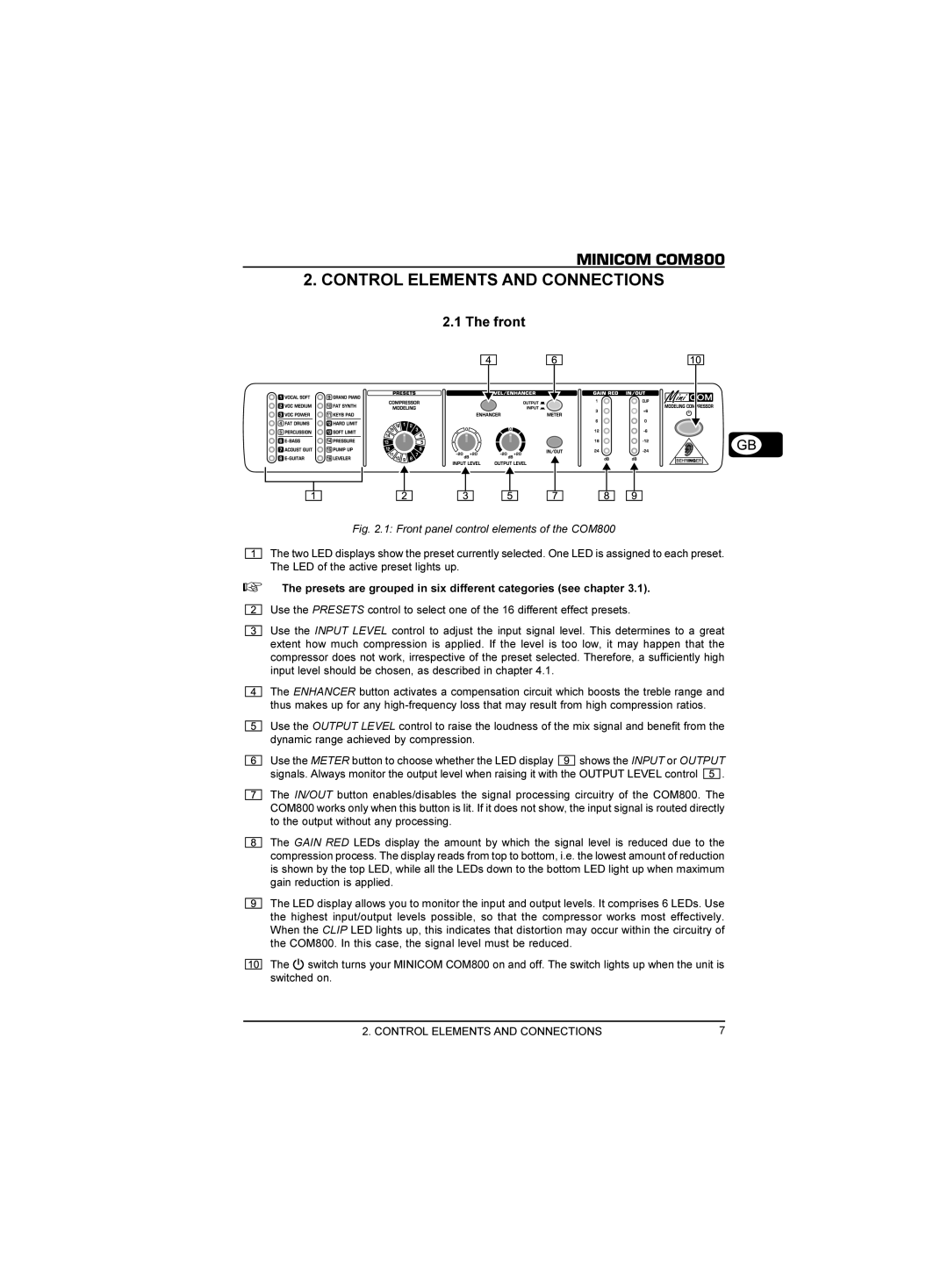
Fig. 2.1: Front panel control elements of the COM800
The two LED displays show the preset currently selected. One LED is assigned to each preset. The LED of the active preset lights up.
+The presets are grouped in six different categories (see chapter 3.1).
Use the PRESETS control to select one of the 16 different effect presets.
Use the INPUT LEVEL control to adjust the input signal level. This determines to a great extent how much compression is applied. If the level is too low, it may happen that the compressor does not work, irrespective of the preset selected. Therefore, a sufficiently high input level should be chosen, as described in chapter 4.1.
The ENHANCER button activates a compensation circuit which boosts the treble range and thus makes up for any
Use the OUTPUT LEVEL control to raise the loudness of the mix signal and benefit from the dynamic range achieved by compression.
Use the METER button to choose whether the LED display ![]() shows the INPUT or OUTPUT
shows the INPUT or OUTPUT
signals. Always monitor the output level when raising it with the OUTPUT LEVEL control ![]()
![]()
![]() .
.
The IN/OUT button enables/disables the signal processing circuitry of the COM800. The COM800 works only when this button is lit. If it does not show, the input signal is routed directly to the output without any processing.
The GAIN RED LEDs display the amount by which the signal level is reduced due to the compression process. The display reads from top to bottom, i.e. the lowest amount of reduction is shown by the top LED, while all the LEDs down to the bottom LED light up when maximum gain reduction is applied.
The LED display allows you to monitor the input and output levels. It comprises 6 LEDs. Use the highest input/output levels possible, so that the compressor works most effectively. When the CLIP LED lights up, this indicates that distortion may occur within the circuitry of the COM800. In this case, the signal level must be reduced.
The ![]() switch turns your MINICOM COM800 on and off. The switch lights up when the unit is switched on.
switch turns your MINICOM COM800 on and off. The switch lights up when the unit is switched on.
2. CONTROL ELEMENTS AND CONNECTIONS | 7 |