AUTOCOM PRO MDX1400
15
The SC FILTER switch activates a highpass filter in the sidechain path and thus limits the influence of low frequencies on the AUTOCOM PRO’s control processes.
16
17
The
The
2.3 Dynamic Enhancer Section
18
18
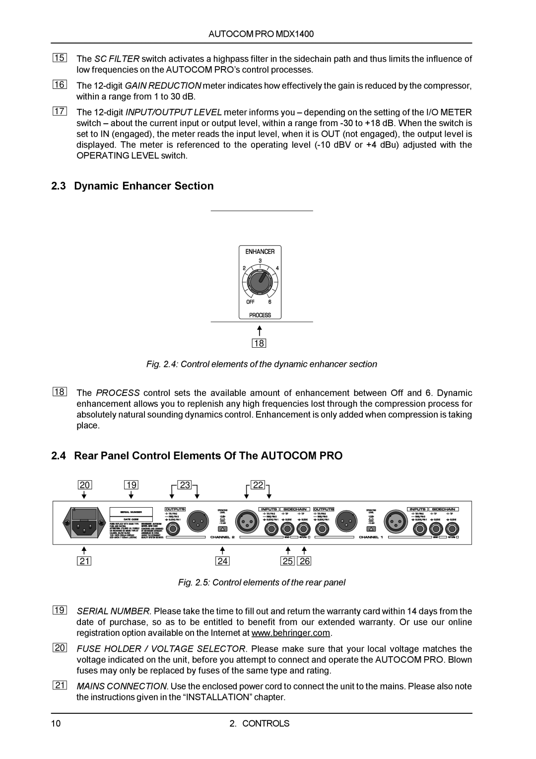
Fig. 2.4: Control elements of the dynamic enhancer section
The PROCESS control sets the available amount of enhancement between Off and 6. Dynamic enhancement allows you to replenish any high frequencies lost through the compression process for absolutely natural sounding dynamics control. Enhancement is only added when compression is taking place.
2.4 Rear Panel Control Elements Of The AUTOCOM PRO
20
19
![]() 23
23![]()
![]()
![]() 22
22 ![]()
![]()
19
20
21
21 |
| 24 |
| 25 |
| 26 |
Fig. 2.5: Control elements of the rear panel
SERIAL NUMBER. Please take the time to fill out and return the warranty card within 14 days from the date of purchase, so as to be entitled to benefit from our extended warranty. Or use our online registration option available on the Internet at www.behringer.com.
FUSE HOLDER / VOLTAGE SELECTOR. Please make sure that your local voltage matches the voltage indicated on the unit, before you attempt to connect and operate the AUTOCOM PRO. Blown fuses may only be replaced by fuses of the same type and rating.
MAINS CONNECTION. Use the enclosed power cord to connect the unit to the mains. Please also note the instructions given in the “INSTALLATION” chapter.
10 | 2. CONTROLS |