DENOISER SNR2000
1.3.1 Front panel
1
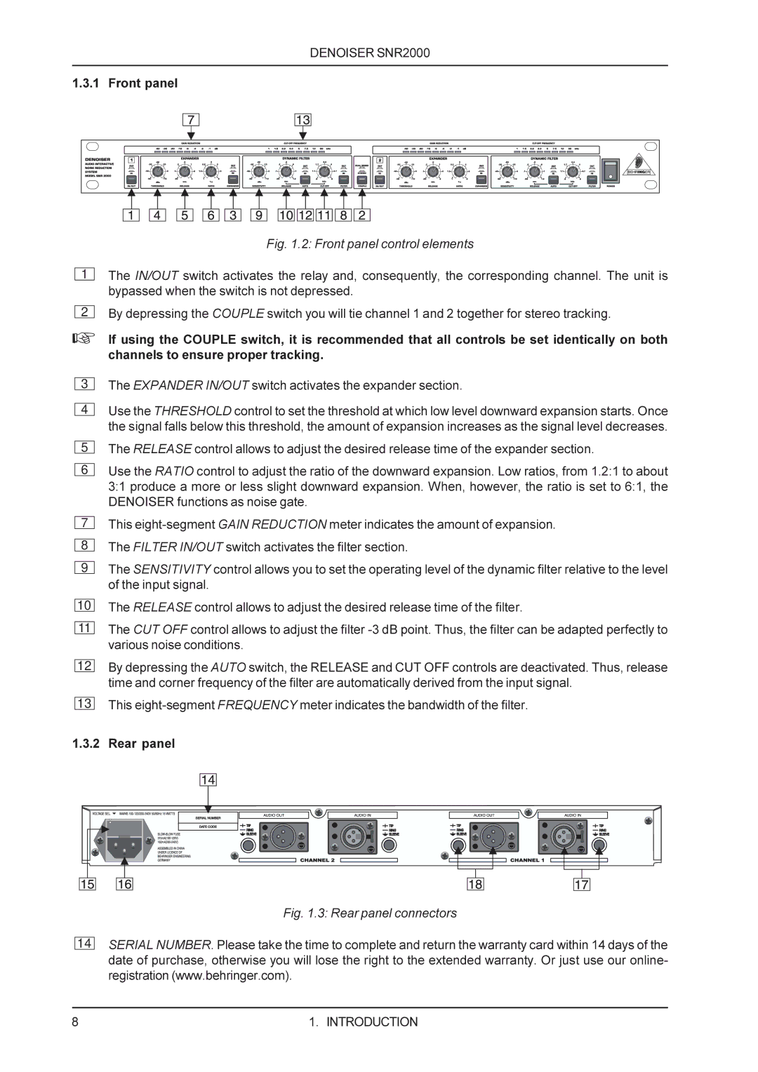
Fig. 1.2: Front panel control elements
The IN/OUT switch activates the relay and, consequently, the corresponding channel. The unit is bypassed when the switch is not depressed.
2
By depressing the COUPLE switch you will tie channel 1 and 2 together for stereo tracking.
+If using the COUPLE switch, it is recommended that all controls be set identically on both channels to ensure proper tracking.
3
4
5
6
7
8
9
10
11
12
13
The EXPANDER IN/OUT switch activates the expander section.
Use the THRESHOLD control to set the threshold at which low level downward expansion starts. Once the signal falls below this threshold, the amount of expansion increases as the signal level decreases.
The RELEASE control allows to adjust the desired release time of the expander section.
Use the RATIO control to adjust the ratio of the downward expansion. Low ratios, from 1.2:1 to about 3:1 produce a more or less slight downward expansion. When, however, the ratio is set to 6:1, the DENOISER functions as noise gate.
This
The SENSITIVITY control allows you to set the operating level of the dynamic filter relative to the level of the input signal.
The RELEASE control allows to adjust the desired release time of the filter.
The CUT OFF control allows to adjust the filter
By depressing the AUTO switch, the RELEASE and CUT OFF controls are deactivated. Thus, release time and corner frequency of the filter are automatically derived from the input signal.
This
1.3.2 Rear panel
14
Fig. 1.3: Rear panel connectors
SERIAL NUMBER. Please take the time to complete and return the warranty card within 14 days of the date of purchase, otherwise you will lose the right to the extended warranty. Or just use our online- registration (www.behringer.com).
8 | 1. INTRODUCTION |
