Bendix Manual Slack Adjusters
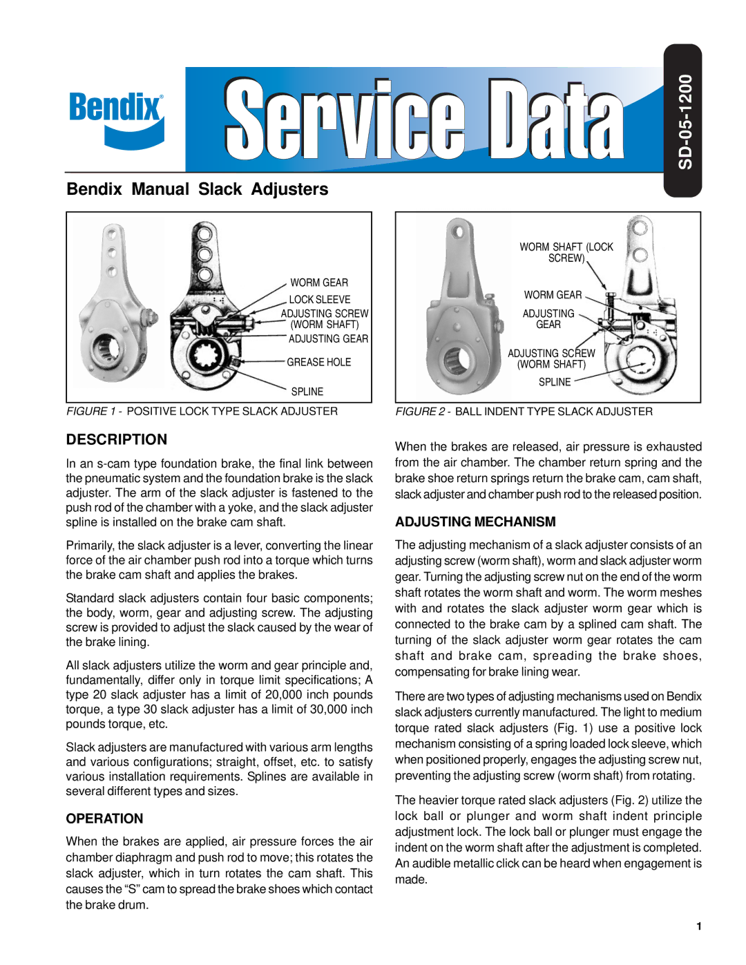
WORM GEAR
LOCK SLEEVE
ADJUSTING SCREW
(WORM SHAFT) ADJUSTING GEAR
GREASE HOLE
SPLINE
FIGURE 1 - POSITIVE LOCK TYPE SLACK ADJUSTER
DESCRIPTION
In an
Primarily, the slack adjuster is a lever, converting the linear force of the air chamber push rod into a torque which turns the brake cam shaft and applies the brakes.
Standard slack adjusters contain four basic components; the body, worm, gear and adjusting screw. The adjusting screw is provided to adjust the slack caused by the wear of the brake lining.
All slack adjusters utilize the worm and gear principle and, fundamentally, differ only in torque limit specifications; A type 20 slack adjuster has a limit of 20,000 inch pounds torque, a type 30 slack adjuster has a limit of 30,000 inch pounds torque, etc.
Slack adjusters are manufactured with various arm lengths and various configurations; straight, offset, etc. to satisfy various installation requirements. Splines are available in several different types and sizes.
OPERATION
When the brakes are applied, air pressure forces the air chamber diaphragm and push rod to move; this rotates the slack adjuster, which in turn rotates the cam shaft. This causes the “S” cam to spread the brake shoes which contact the brake drum.
SD-05-1200
WORM SHAFT (LOCK
SCREW)
WORM GEAR
ADJUSTING
GEAR
ADJUSTING SCREW
(WORM SHAFT)
SPLINE
FIGURE 2 - BALL INDENT TYPE SLACK ADJUSTER
When the brakes are released, air pressure is exhausted from the air chamber. The chamber return spring and the brake shoe return springs return the brake cam, cam shaft, slack adjuster and chamber push rod to the released position.
ADJUSTING MECHANISM
The adjusting mechanism of a slack adjuster consists of an adjusting screw (worm shaft), worm and slack adjuster worm gear. Turning the adjusting screw nut on the end of the worm shaft rotates the worm shaft and worm. The worm meshes with and rotates the slack adjuster worm gear which is connected to the brake cam by a splined cam shaft. The turning of the slack adjuster worm gear rotates the cam shaft and brake cam, spreading the brake shoes, compensating for brake lining wear.
There are two types of adjusting mechanisms used on Bendix slack adjusters currently manufactured. The light to medium torque rated slack adjusters (Fig. 1) use a positive lock mechanism consisting of a spring loaded lock sleeve, which when positioned properly, engages the adjusting screw nut, preventing the adjusting screw (worm shaft) from rotating.
The heavier torque rated slack adjusters (Fig. 2) utilize the lock ball or plunger and worm shaft indent principle adjustment lock. The lock ball or plunger must engage the indent on the worm shaft after the adjustment is completed. An audible metallic click can be heard when engagement is made.
1