Using the Positive Lock Slack Adjuster Mechanism: (Fig. 1)
Wipe the adjusting screw nut and locking sleeve area clean. Position wrench or socket over the adjusting screw and disengage the locking sleeve by depressing the lock sleeve. Make the necessary adjustment by turning the adjusting screw with the locking sleeve depressed.
When adjustment is completed, the adjusting screw nut should be positioned so the locking sleeve engages the adjusting screw nut, thus locking the adjusting screw in place. DO NOT ATTEMPT TO TURN THE ADJUSTING SCREW WITHOUT FULLY DEPRESSING THE LOCK SLEEVE.
Using the Ball Indent Slack Adjuster Mechanism: (Fig. 2)
Before proceeding with adjustment, measure distance from top of lock screw head to slack adjuster body.
To adjust, back off lock screw (counter clockwise) and make necessary adjustment by turning the adjusting screw. After adjustment is complete, retighten lock screw, making certain that lock ball is engaged on the plunger shaft. (Proper engagement can be confirmed by checking the measurement from the top of the lock screw head to the slack adjuster body. It should be the same before and after the adjustment.)
PROCEDURE
Vehicle brakes should normally be adjusted using the vehicle or brake manufacturer’s recommendations. If they are not available, the following can be used:
1.Bring the vehicle to rest on a level surface and chock the wheels.
2.Mechanically release (“cage”) the spring brakes.
BRAKE ADJUSTMENT CHECK
A. PREFERRED METHOD
Determine the brake chamber size. Make a 100 psi application to the service brakes and measure the push rod stroke. Using the chart (Fig. 3) compare the actual chamber stroke to the recommended maximum stroke to determine if brake adjustment is required.
| CLAMP RING TYPE CHAMBER DATA |
| |||
|
| (Dimensions in inches) |
| ||
|
|
|
| Max. | Max. Stroke |
|
|
|
| Stroke | at Which |
| Effective | * |
| With | Brakes |
| Area | Outside | Max. | Brakes | Should Be |
Type | (Sq. In.) | Diameter | Stroke | Adjusted | Readjusted |
6 | 6 | Should | |||
9 | 9 | be as | |||
12 | 12 | short as | |||
16 | 16 | possible | |||
20 | 20 | without | |||
24 | 24 | brakes | |||
30 | 30 | dragging | 2 | ||
36 | 36 | 9 | 3 |
| |
*Dimensions listed do not include capscrew head projections
for rotochambers and bolt clamp projections for clamp type brake chambers.
FIGURE 3
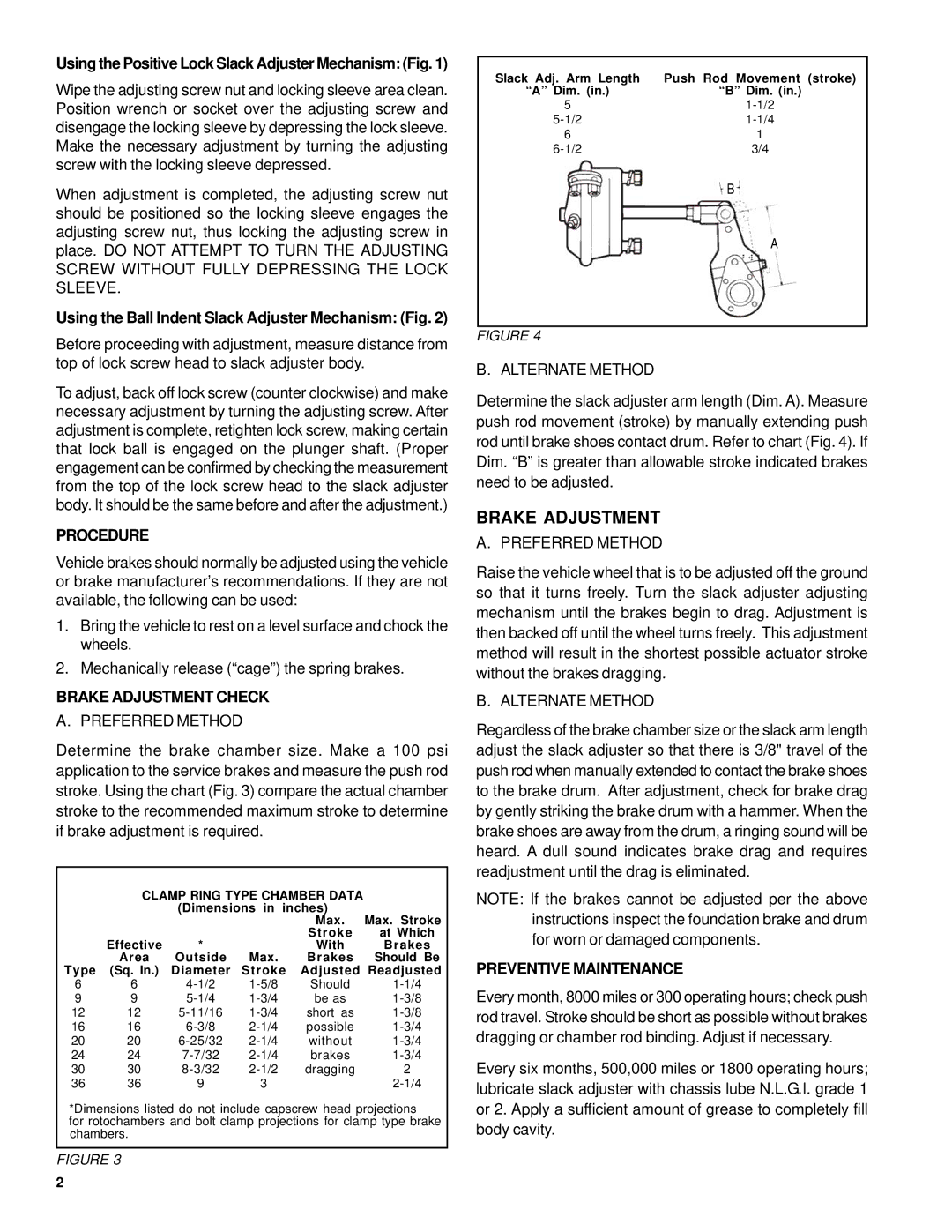
Slack Adj. Arm Length | Push Rod Movement (stroke) |
“A” Dim. (in.) | “B” Dim. (in.) |
5 | |
6 | 1 |
3/4 |
B
A
FIGURE 4
B. ALTERNATE METHOD
Determine the slack adjuster arm length (Dim. A). Measure push rod movement (stroke) by manually extending push rod until brake shoes contact drum. Refer to chart (Fig. 4). If Dim. “B” is greater than allowable stroke indicated brakes need to be adjusted.
BRAKE ADJUSTMENT
A. PREFERRED METHOD
Raise the vehicle wheel that is to be adjusted off the ground so that it turns freely. Turn the slack adjuster adjusting mechanism until the brakes begin to drag. Adjustment is then backed off until the wheel turns freely. This adjustment method will result in the shortest possible actuator stroke without the brakes dragging.
B. ALTERNATE METHOD
Regardless of the brake chamber size or the slack arm length adjust the slack adjuster so that there is 3/8" travel of the push rod when manually extended to contact the brake shoes to the brake drum. After adjustment, check for brake drag by gently striking the brake drum with a hammer. When the brake shoes are away from the drum, a ringing sound will be heard. A dull sound indicates brake drag and requires readjustment until the drag is eliminated.
NOTE: If the brakes cannot be adjusted per the above instructions inspect the foundation brake and drum for worn or damaged components.
PREVENTIVE MAINTENANCE
Every month, 8000 miles or 300 operating hours; check push rod travel. Stroke should be short as possible without brakes dragging or chamber rod binding. Adjust if necessary.
Every six months, 500,000 miles or 1800 operating hours; lubricate slack adjuster with chassis lube N.L.G.I. grade 1 or 2. Apply a sufficient amount of grease to completely fill body cavity.
2