engine be in operation, EXTREME CAUTION should be used to prevent personal injury resulting from contact with moving, rotating, leaking, heated or electrically charged components.
3.Do not attempt to install, remove, disassemble or assemble a component until you have read and thoroughly understand the recommended procedures. Use only the proper tools and observe all precautions pertaining to use of those tools.
4.If the work is being performed on the vehicle’s air brake system, or any auxiliary pressurized air systems, make certain to drain the air pressure from all reservoirs before beginning ANY work on the vehicle. If the vehicle is equipped with an
5. Fo ll ow in g t h e ve hi c l e m a nu f a c t u r e r ’s recommended procedures, deactivate the electrical system in a manner that safely removes all electrical power from the vehicle.
6.Never exceed manufacturer’s recommended pressures.
7.Never connect or disconnect a hose or line containing pressure; it may whip. Never remove a component or plug unless you are certain all system pressure has been depleted.
8.Use only genuine Bendix® replacement parts, components and kits. Replacement hardware, tubing, hose, fittings, etc. must be of equivalent size, type and strength as original equipment and be designed specifically for such applications and systems.
9.Components with stripped threads or damaged parts should be replaced rather than repaired. Do not attempt repairs requiring machining or welding unless specifically stated and approved by the vehicle and component manufacturer.
10.Prior to returning the vehicle to service, make certain all components and systems are restored to their proper operating condition.
11.For vehicles with Automatic Traction Control (ATC), the ATC function must be disabled (ATC indicator lamp should be ON) prior to performing any vehicle maintenance where one or more wheels on a drive axle are lifted off the ground and moving.
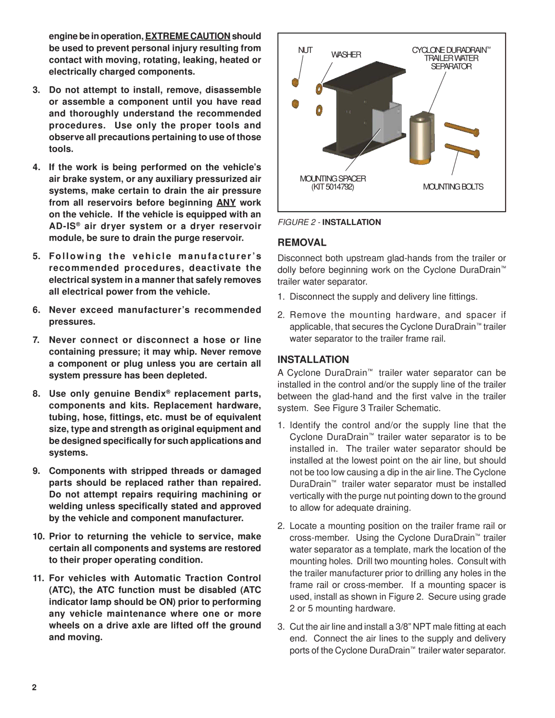
NUT | WASHER | CYCLONE DURADRAIN™ |
| TRAILER WATER | |
|
| SEPARATOR |
MOUNTING SPACER | MOUNTING BOLTS |
(KIT 5014792) |
FIGURE 2 - INSTALLATION
REMOVAL
Disconnect both upstream
1.Disconnect the supply and delivery line fittings.
2.Remove the mounting hardware, and spacer if applicable, that secures the Cyclone DuraDrain™ trailer water separator to the trailer frame rail.
INSTALLATION
A Cyclone DuraDrain™ trailer water separator can be installed in the control and/or the supply line of the trailer between the
1.Identify the control and/or the supply line that the Cyclone DuraDrain™ trailer water separator is to be installed in. The trailer water separator should be installed at the lowest point on the air line, but should not be too low causing a dip in the air line. The Cyclone DuraDrain™ trailer water separator must be installed vertically with the purge nut pointing down to the ground to allow for adequate draining.
2.Locate a mounting position on the trailer frame rail or
3.Cut the air line and install a 3/8” NPT male fitting at each end. Connect the air lines to the supply and delivery ports of the Cyclone DuraDrain™ trailer water separator.
2