EUROSTYLE ROCKER SWITCH CONTROL
(Part# ES2000)
INSTALLATION INSTRUCTIONS
1.Before you drill any holes, read the entire instruction sheet.
2.Unsnap the bezel from the control. Using the bezel locate the position for the control at the helm. Check carefully to make sure there are no obstructions behind the dashboard before drilling any holes.
3.The bezel requires a footprint of
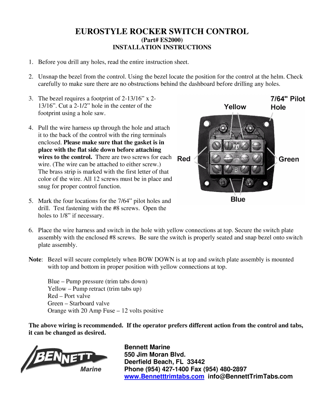
4.Pull the wire harness up through the hole and attach it to the back of the control with the ring terminals enclosed. Please make sure that the gasket is in place with the flat side down before attaching wires to the control. There are two screws for each wire. (The wire can be attached to either screw.) The brass strip is marked with the first letter of that color of the wire. All 12 screws must be in place and snug for proper control function.
5.Mark the four locations for the 7/64” pilot holes and drill. Test fastening with the #8 screws. Open the holes to 1/8” if necessary.
6.Place the wire harness and switch in the hole with yellow connections at top. Secure the switch plate assembly with the enclosed #8 screws. Be sure the switch is properly seated and snap bezel onto switch plate assembly.
Note: Bezel will secure completely when BOW DOWN is at top and switch plate assembly is mounted with top and bottom in proper position with yellow connections at top.
Blue – Pump pressure (trim tabs down)
Yellow – Pump retract (trim tabs up)
Red – Port valve
Green – Starboard valve
Orange with 20 Amp Fuse – 12 volts positive
The above wiring is recommended. If the operator prefers different action from the control and tabs, it can be changed as desired.
Bennett Marine
550 Jim Moran Blvd. Deerfield Beach, FL 33442
Phone (954)