18P0, 43Z3 specifications
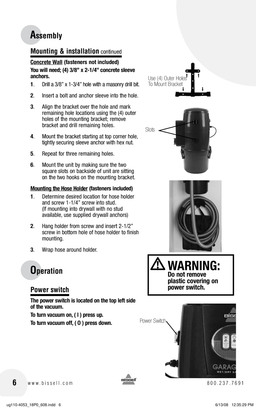
The Bissell 43Z3,18PO is a powerful and versatile vacuum cleaner designed to tackle a variety of cleaning tasks around the home. Known for its efficient performance and user-friendly features, this model is ideal for pet owners, families, and anyone looking to maintain a clean living space.One of the standout features of the Bissell 43Z3,18PO is its strong suction power. The vacuum is equipped with a high-performance motor that enables it to lift dirt, dust, and pet hair from carpets, upholstery, and hard floors with ease. This makes it particularly useful for households with pets, where hair and dander can accumulate quickly.
The Bissell 43Z3,18PO also incorporates advanced multi-cyclonic technology. This innovation ensures that suction power remains strong over time by effectively separating dirt and debris from the air. As a result, users can enjoy consistent, powerful suction throughout their cleaning sessions, without worrying about loss of performance.
Convenience is a key consideration in the design of this vacuum cleaner. The Bissell 43Z3,18PO features a lightweight design, making it easy to carry and maneuver around the home. The ergonomic handle enhances user comfort, while the upright posture allows for effortless cleaning of both low and high surfaces.
Additionally, this model comes with a variety of attachments, including a crevice tool and dusting brush. These accessories make it easier to clean tight spaces, corners, and delicate surfaces, ensuring that every area of the home is covered.
The filtration system in the Bissell 43Z3,18PO is designed to capture allergens and fine particles, making it a great choice for allergy sufferers. The washable filter can be easily cleaned and reused, promoting sustainability while maintaining the vacuum's performance.
Another attractive feature of the Bissell 43Z3,18PO is its easy-to-empty dirt tank. By eliminating the hassle of dealing with bags, users can quickly dispose of collected debris with minimal mess.
In summary, the Bissell 43Z3,18PO combines powerful suction, advanced technologies, and user-friendly features to deliver an exceptional cleaning experience. Its lightweight design, versatile attachments, and efficient filtration system make it a perfect choice for anyone seeking a reliable vacuum cleaner that can handle daily cleaning challenges with ease.

