2 | 5 | 11 | ||||
1 |
| 6 |
|
| ||
|
|
|
| |||
|
| 9 |
| |||
4 |
| 7 |
|
|
|
|
|
|
|
|
| ||
|
|
|
|
|
| |
|
|
|
|
|
| |
|
|
|
| 10 | ||
|
|
|
| |||
|
|
| ||||
|
|
|
|
| ||
3 |
| 8 |
| |||
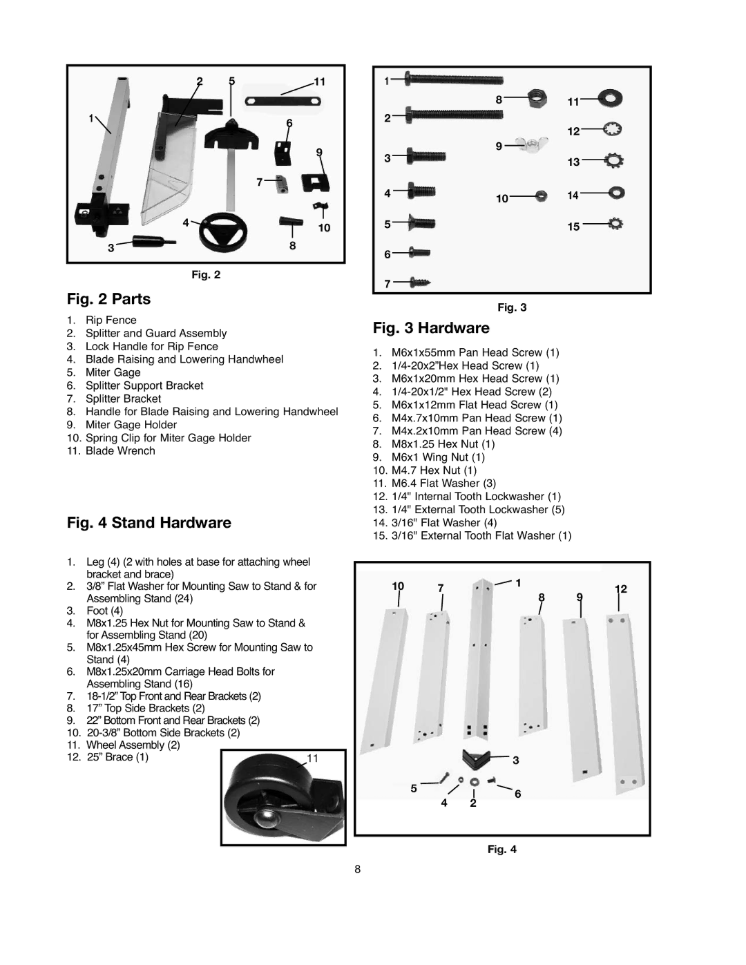
Fig. 2
Fig. 2 Parts
1.Rip Fence
2.Splitter and Guard Assembly
3.Lock Handle for Rip Fence
4.Blade Raising and Lowering Handwheel
5.Miter Gage
6.Splitter Support Bracket
7.Splitter Bracket
8.Handle for Blade Raising and Lowering Handwheel
9.Miter Gage Holder
10.Spring Clip for Miter Gage Holder
11.Blade Wrench
Fig. 4 Stand Hardware
1.Leg (4) (2 with holes at base for attaching wheel bracket and brace)
2.3/8” Flat Washer for Mounting Saw to Stand & for Assembling Stand (24)
3.Foot (4)
4.M8x1.25 Hex Nut for Mounting Saw to Stand & for Assembling Stand (20)
5.M8x1.25x45mm Hex Screw for Mounting Saw to Stand (4)
6.M8x1.25x20mm Carriage Head Bolts for Assembling Stand (16)
7.
8.17” Top Side Brackets (2)
9.22” Bottom Front and Rear Brackets (2)
10.
11.Wheel Assembly (2)
12. 25” Brace (1) | 11 |
|
|
1 |
|
|
|
|
|
|
|
|
|
|
|
8 |
|
|
| 11 | |||||||
2 |
|
|
| ||||||||
|
|
| |||||||||
|
|
|
|
|
|
|
|
| 12 | ||
|
|
|
|
|
|
|
|
| |||
|
|
|
|
|
|
|
|
|
| ||
3 | 9 |
|
|
| 13 | ||||||
|
|
| |||||||||
|
|
|
|
|
|
|
|
| |||
|
|
|
|
|
|
|
|
| |||
|
|
|
|
|
|
|
|
|
| ||
4 |
|
|
|
|
|
|
|
|
|
| 14 |
10 |
|
| |||||||||
|
|
| |||||||||
|
|
|
|
| |||||||
5 |
|
|
|
|
|
|
|
|
| 15 | |
|
|
|
|
|
|
|
|
| |||
6 |
|
|
|
|
|
|
|
|
|
|
|
|
|
|
|
|
|
|
|
|
|
| |
7
Fig. 3
Fig. 3 Hardware
1.M6x1x55mm Pan Head Screw (1)
2.
3.M6x1x20mm Hex Head Screw (1)
4.
5.M6x1x12mm Flat Head Screw (1)
6.M4x.7x10mm Pan Head Screw (1)
7.M4x.2x10mm Pan Head Screw (4)
8.M8x1.25 Hex Nut (1)
9.M6x1 Wing Nut (1)
10.M4.7 Hex Nut (1)
11.M6.4 Flat Washer (3)
12.1/4" Internal Tooth Lockwasher (1)
13.1/4" External Tooth Lockwasher (5)
14.3/16" Flat Washer (4)
15.3/16" External Tooth Flat Washer (1)
10 | 7 | 1 | 12 | ||
|
| 8 | 9 |
|
|
|
|
|
|
| |
|
|
|
|
|
|
|
|
|
|
|
|
| 3 |
5 | 6 |
|
42
Fig. 4
8
