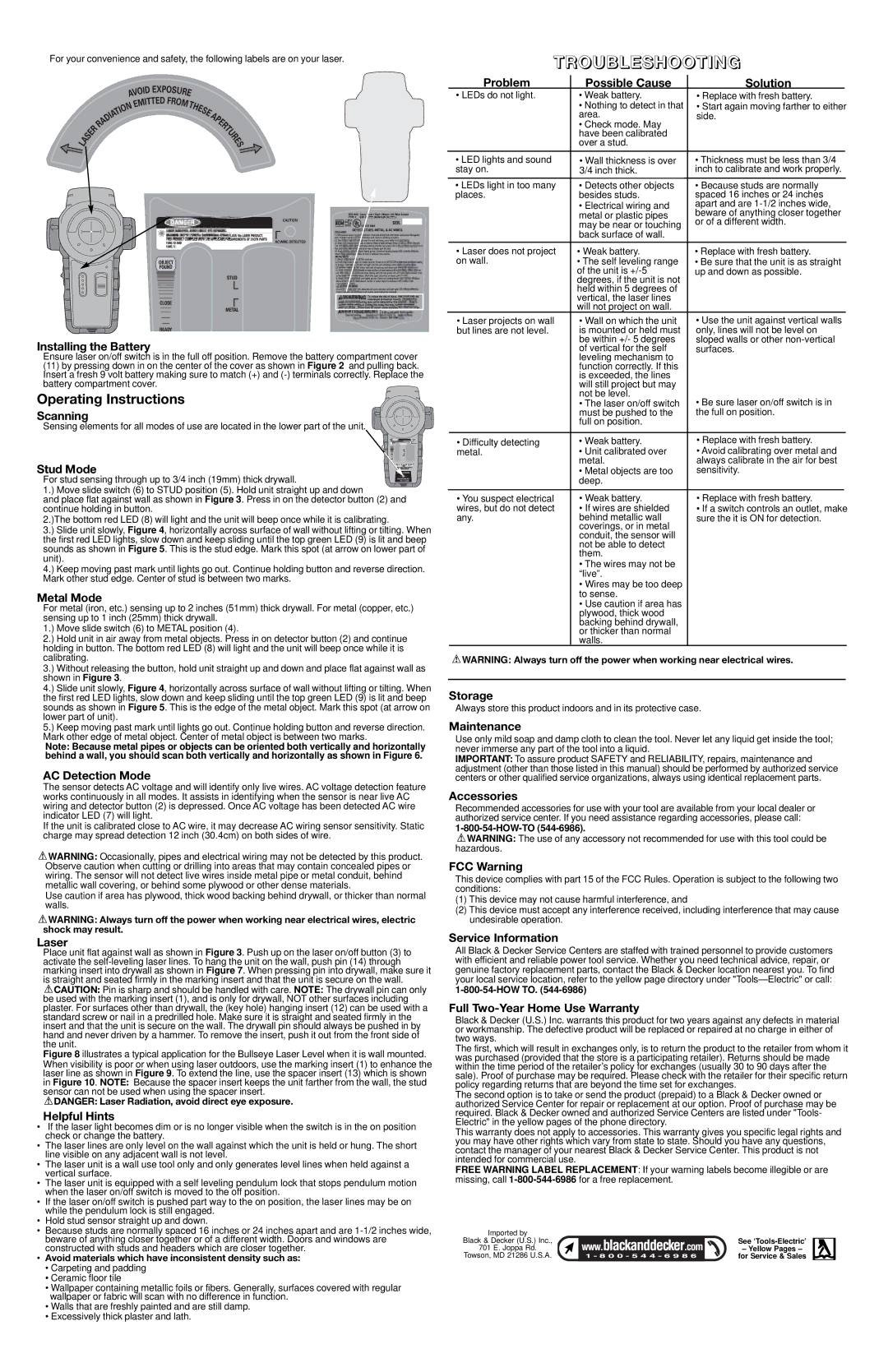
For your convenience and safety, the following labels are on your laser.
Installing the Battery
Ensure laser on/off switch is in the full off position. Remove the battery compartment cover
(11)by pressing down in on the center of the cover as shown in Figure 2 and pulling back. Insert a fresh 9 volt battery making sure to match (+) and
Operating Instructions
Scanning
Sensing elements for all modes of use are located in the lower part of the unit.
Stud Mode
For stud sensing through up to 3/4 inch (19mm) thick drywall.
1.) Move slide switch (6) to STUD position (5). Hold unit straight up and down
and place flat against wall as shown in Figure 3. Press in on the detector button (2) and continue holding in button.
2.)The bottom red LED (8) will light and the unit will beep once while it is calibrating.
3.) Slide unit slowly, Figure 4, horizontally across surface of wall without lifting or tilting. When the first red LED lights, slow down and keep sliding until the top green LED (9) is lit and beep sounds as shown in Figure 5. This is the stud edge. Mark this spot (at arrow on lower part of unit).
4.) Keep moving past mark until lights go out. Continue holding button and reverse direction. Mark other stud edge. Center of stud is between two marks.
Metal Mode
For metal (iron, etc.) sensing up to 2 inches (51mm) thick drywall. For metal (copper, etc.) sensing up to 1 inch (25mm) thick drywall.
1.) Move slide switch (6) to METAL position (4).
2.) Hold unit in air away from metal objects. Press in on detector button (2) and continue holding in button. The bottom red LED (8) will light and the unit will beep once while it is calibrating.
3.) Without releasing the button, hold unit straight up and down and place flat against wall as shown in Figure 3.
4.) Slide unit slowly, Figure 4, horizontally across surface of wall without lifting or tilting. When the first red LED lights, slow down and keep sliding until the top green LED (9) is lit and beep sounds as shown in Figure 5. This is the edge of the metal object. Mark this spot (at arrow on lower part of unit).
5.) Keep moving past mark until lights go out. Continue holding button and reverse direction. Mark other edge of metal object. Center of metal object is between two marks.
Note: Because metal pipes or objects can be oriented both vertically and horizontally behind a wall, you should scan both vertically and horizontally as shown in Figure 6.
AC Detection Mode
The sensor detects AC voltage and will identify only live wires. AC voltage detection feature works continuously in all modes. It assists in identifying when the sensor is near live AC wiring and detector button (2) is depressed. Once AC voltage has been detected AC wire indicator LED (7) will light.
If the unit is calibrated close to AC wire, it may decrease AC wiring sensor sensitivity. Static charge may spread detection 12 inch (30.4cm) on both sides of wire.
![]() WARNING: Occasionally, pipes and electrical wiring may not be detected by this product. Observe caution when cutting or drilling into areas that may contain concealed pipes or wiring. The sensor will not detect live wires inside metal pipe or metal conduit, behind metallic wall covering, or behind some plywood or other dense materials.
WARNING: Occasionally, pipes and electrical wiring may not be detected by this product. Observe caution when cutting or drilling into areas that may contain concealed pipes or wiring. The sensor will not detect live wires inside metal pipe or metal conduit, behind metallic wall covering, or behind some plywood or other dense materials.
Use caution if area has plywood, thick wood backing behind drywall, or thicker than normal walls.
![]() WARNING: Always turn off the power when working near electrical wires, electric shock may result.
WARNING: Always turn off the power when working near electrical wires, electric shock may result.
Laser
Place unit flat against wall as shown in Figure 3. Push up on the laser on/off button (3) to activate the
![]() CAUTION: Pin is sharp and should be handled with care. NOTE: The drywall pin can only be used with the marking insert (1), and is only for drywall, NOT other surfaces including plaster. For surfaces other than drywall, the (key hole) hanging insert (12) can be used with a standard screw or nail in a predrilled hole. Make sure it is straight and seated firmly in the insert and that the unit is secure on the wall. The drywall pin should always be pushed in by hand and never driven by a hammer. To remove the insert, push it out from the front side of the unit.
CAUTION: Pin is sharp and should be handled with care. NOTE: The drywall pin can only be used with the marking insert (1), and is only for drywall, NOT other surfaces including plaster. For surfaces other than drywall, the (key hole) hanging insert (12) can be used with a standard screw or nail in a predrilled hole. Make sure it is straight and seated firmly in the insert and that the unit is secure on the wall. The drywall pin should always be pushed in by hand and never driven by a hammer. To remove the insert, push it out from the front side of the unit.
Figure 8 illustrates a typical application for the Bullseye Laser Level when it is wall mounted.
When visibility is poor or when using laser outdoors, use the marking insert (1) to enhance the laser line as shown in Figure 9. To extend the line, use the spacer insert (13) which is shown in Figure 10. NOTE: Because the spacer insert keeps the unit farther from the wall, the stud sensor can not be used when using the spacer insert.
![]() DANGER: Laser Radiation, avoid direct eye exposure.
DANGER: Laser Radiation, avoid direct eye exposure.
Helpful Hints
•If the laser light becomes dim or is no longer visible when the switch is in the on position check or change the battery.
•The laser lines are only level on the wall against which the unit is held or hung. The short line visible on any adjacent wall is not level.
•The laser unit is a wall use tool only and only generates level lines when held against a vertical surface.
•The laser unit is equipped with a self leveling pendulum lock that stops pendulum motion when the laser on/off switch is moved to the off position.
•If the laser on/off switch is pushed part way to the on position, the laser lines may be on while the pendulum lock is still engaged.
•Hold stud sensor straight up and down.
•Because studs are normally spaced 16 inches or 24 inches apart and are
•Avoid materials which have inconsistent density such as:
•Carpeting and padding
•Ceramic floor tile
•Wallpaper containing metallic foils or fibers. Generally, surfaces covered with regular wallpaper or fabric will scan with no difference in function.
•Walls that are freshly painted and are still damp.
•Excessively thick plaster and lath.
TROUBLESHOOTING
| Problem |
| Possible Cause | Solution |
| ||
| • LEDs do not light. |
| • Weak battery. | • Replace with fresh battery. | |||
|
|
| • Nothing to detect in that | • Start again moving farther to either | |||
|
|
| area. | side. | |||
|
|
| • Check mode. May |
|
|
| |
|
|
| have been calibrated |
|
|
| |
|
|
| over a stud. |
|
|
| |
|
|
|
|
|
|
|
|
|
|
|
|
|
|
|
|
| • LED lights and sound |
|
|
| • Thickness must be less than 3/4 |
| |
|
| • Wall thickness is over |
| ||||
| stay on. |
| 3/4 inch thick. |
| inch to calibrate and work properly. |
| |
|
|
|
|
|
|
|
|
|
|
|
|
|
|
|
|
| • LEDs light in too many |
| • Detects other objects | • Because studs are normally | |||
| places. |
| besides studs. | spaced 16 inches or 24 inches | |||
|
|
| • Electrical wiring and | apart and are | |||
|
|
| metal or plastic pipes | beware of anything closer together | |||
|
|
| may be near or touching | or of a different width. | |||
|
|
| back surface of wall. |
|
|
| |
|
|
|
|
|
|
|
|
| • Laser does not project |
| • Weak battery. | • Replace with fresh battery. | |||
| on wall. |
| • The self leveling range | • Be sure that the unit is as straight | |||
|
|
| of the unit is | up and down as possible. | |||
|
|
| degrees, if the unit is not |
|
|
| |
|
|
| held within 5 degrees of |
|
|
| |
|
|
| vertical, the laser lines |
|
|
| |
|
|
| will not project on wall. |
|
|
| |
| • Laser projects on wall |
| • Wall on which the unit | • Use the unit against vertical walls | |||
| but lines are not level. |
| is mounted or held must | only, lines will not be level on | |||
|
|
| be within +/- 5 degrees | sloped walls or other | |||
|
|
| of vertical for the self | surfaces. | |||
|
|
| leveling mechanism to |
|
|
| |
|
|
| function correctly. If this |
|
|
| |
|
|
| is exceeded, the lines |
|
|
| |
|
|
| will still project but may |
|
|
| |
|
|
| not be level. | • Be sure laser on/off switch is in | |||
|
|
| • The laser on/off switch | ||||
|
|
| must be pushed to the | the full on position. | |||
|
|
| full on position. |
|
|
| |
|
|
|
|
|
| ||
| • Difficulty detecting |
| • Weak battery. | • Replace with fresh battery. | |||
| metal. |
| • Unit calibrated over | • Avoid calibrating over metal and | |||
|
|
| metal. | always calibrate in the air for best | |||
|
|
| • Metal objects are too | sensitivity. | |||
|
|
| deep. |
|
|
| |
|
|
|
|
|
|
| |
| • You suspect electrical |
| • Weak battery. | • Replace with fresh battery. | |||
| wires, but do not detect |
| • If wires are shielded | • If a switch controls an outlet, make | |||
| any. |
| behind metallic wall | sure the it is ON for detection. | |||
|
|
| coverings, or in metal |
|
|
| |
|
|
| conduit, the sensor will |
|
|
| |
|
|
| not be able to detect |
|
|
| |
|
|
| them. |
|
|
| |
|
|
| • The wires may not be |
|
|
| |
|
|
| “live”. |
|
|
| |
|
|
| • Wires may be too deep |
|
|
| |
|
|
| to sense. |
|
|
| |
|
|
| • Use caution if area has |
|
|
| |
|
|
| plywood, thick wood |
|
|
| |
|
|
| backing behind drywall, |
|
|
| |
|
|
| or thicker than normal |
|
|
| |
|
|
| walls. |
|
|
| |
![]() WARNING: Always turn off the power when working near electrical wires.
WARNING: Always turn off the power when working near electrical wires.
Storage
Always store this product indoors and in its protective case.
Maintenance
Use only mild soap and damp cloth to clean the tool. Never let any liquid get inside the tool; never immerse any part of the tool into a liquid.
IMPORTANT: To assure product SAFETY and RELIABILITY, repairs, maintenance and adjustment (other than those listed in this manual) should be performed by authorized service centers or other qualified service organizations, always using identical replacement parts.
Accessories
Recommended accessories for use with your tool are available from your local dealer or authorized service center. If you need assistance regarding accessories, please call:
![]() WARNING: The use of any accessory not recommended for use with this tool could be hazardous.
WARNING: The use of any accessory not recommended for use with this tool could be hazardous.
FCC Warning
This device complies with part 15 of the FCC Rules. Operation is subject to the following two conditions:
(1)This device may not cause harmful interference, and
(2)This device must accept any interference received, including interference that may cause undesirable operation.
Service Information
All Black & Decker Service Centers are staffed with trained personnel to provide customers with efficient and reliable power tool service. Whether you need technical advice, repair, or genuine factory replacement parts, contact the Black & Decker location nearest you. To find your local service location, refer to the yellow page directory under
Full Two-Year Home Use Warranty
Black & Decker (U.S.) Inc. warrants this product for two years against any defects in material or workmanship. The defective product will be replaced or repaired at no charge in either of two ways.
The first, which will result in exchanges only, is to return the product to the retailer from whom it was purchased (provided that the store is a participating retailer). Returns should be made within the time period of the retailer’s policy for exchanges (usually 30 to 90 days after the sale). Proof of purchase may be required. Please check with the retailer for their specific return policy regarding returns that are beyond the time set for exchanges.
The second option is to take or send the product (prepaid) to a Black & Decker owned or authorized Service Center for repair or replacement at our option. Proof of purchase may be required. Black & Decker owned and authorized Service Centers are listed under "Tools- Electric" in the yellow pages of the phone directory.
This warranty does not apply to accessories. This warranty gives you specific legal rights and you may have other rights which vary from state to state. Should you have any questions, contact the manager of your nearest Black & Decker Service Center. This product is not intended for commercial use.
FREE WARNING LABEL REPLACEMENT: If your warning labels become illegible or are missing, call
Imported by |
|
| |
Black & Decker (U.S.) Inc., |
| See | |
701 | E. Joppa Rd. |
| – Yellow Pages – |
Towson, | MD 21286 U.S.A. |
| for Service & Sales |