DISCONNECT MACHINE FROM POWER SOURCE.
TABLE INSERT ADJUSTMENT
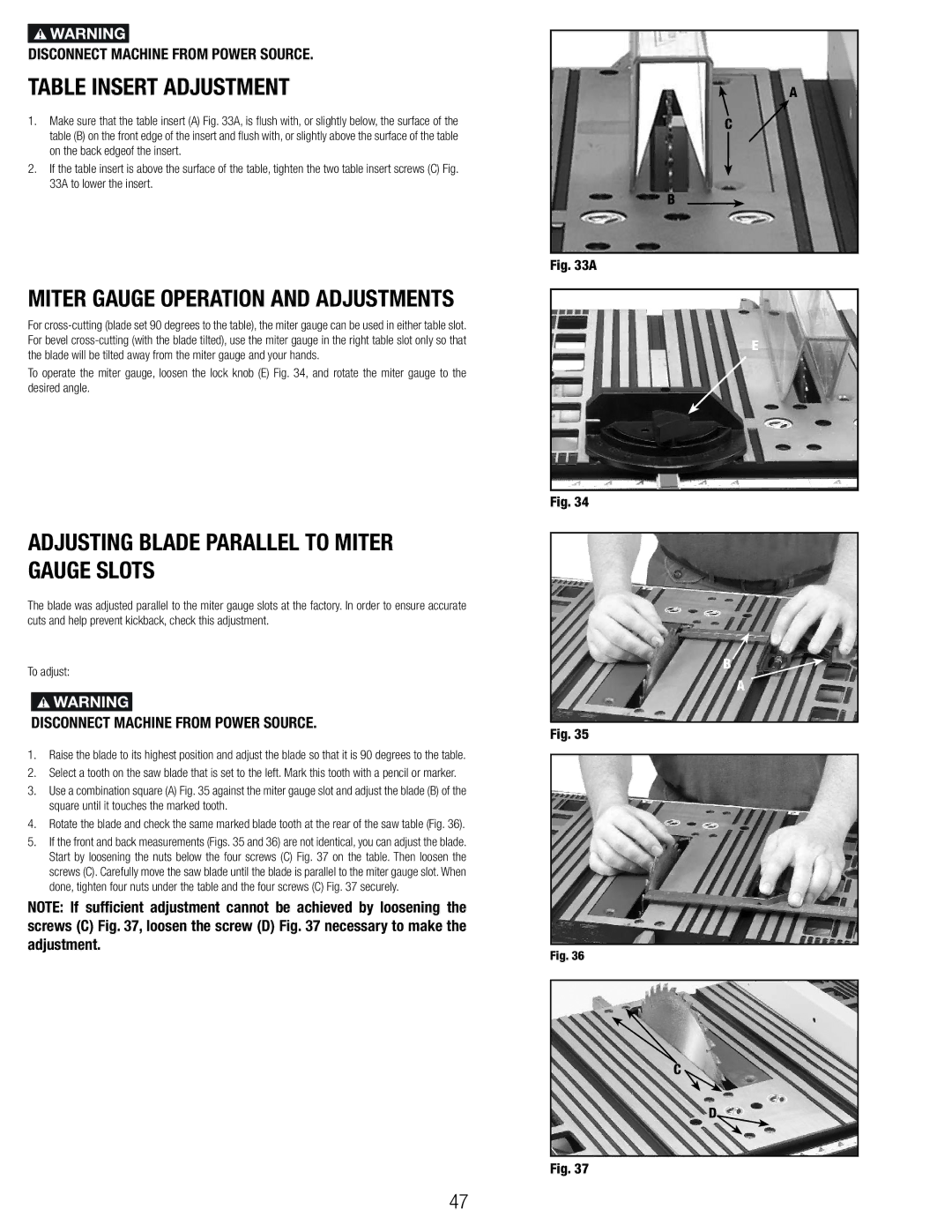
1.Make sure that the table insert (A) Fig. 33A, is flush with, or slightly below, the surface of the table (B) on the front edge of the insert and flush with, or slightly above the surface of the table on the back edgeof the insert.
2.If the table insert is above the surface of the table, tighten the two table insert screws (C) Fig. 33A to lower the insert.
MITER GAUGE OPERATION AND ADJUSTMENTS
For
To operate the miter gauge, loosen the lock knob (E) Fig. 34, and rotate the miter gauge to the desired angle.
ADJUSTING BLADE PARALLEL TO MITER GAUGE SLOTS
The blade was adjusted parallel to the miter gauge slots at the factory. In order to ensure accurate cuts and help prevent kickback, check this adjustment.
To adjust:
DISCONNECT MACHINE FROM POWER SOURCE.
1.Raise the blade to its highest position and adjust the blade so that it is 90 degrees to the table.
2.Select a tooth on the saw blade that is set to the left. Mark this tooth with a pencil or marker.
3.Use a combination square (A) Fig. 35 against the miter gauge slot and adjust the blade (B) of the square until it touches the marked tooth.
4.Rotate the blade and check the same marked blade tooth at the rear of the saw table (Fig. 36).
5.If the front and back measurements (Figs. 35 and 36) are not identical, you can adjust the blade. Start by loosening the nuts below the four screws (C) Fig. 37 on the table. Then loosen the screws (C). Carefully move the saw blade until the blade is parallel to the miter gauge slot. When done, tighten four nuts under the table and the four screws (C) Fig. 37 securely.
NOTE: If sufficient adjustment cannot be achieved by loosening the screws (C) Fig. 37, loosen the screw (D) Fig. 37 necessary to make the adjustment.
A
C
B
Fig. 33A
E
Fig. 34
B
A
Fig. 35
Fig. 36
C
D
Fig. 37
47