ATTACHING BLADE GUARD AND SPLITTER ASSEMBLY
DISCONNECT MACHINE FROM POWER SOURCE.
PROPERLY ALIGN THE BLADE GUARD AND SPLITTER ASSEMBLY WITH THE SAW BLADE TO PREVENT KICKBACK.
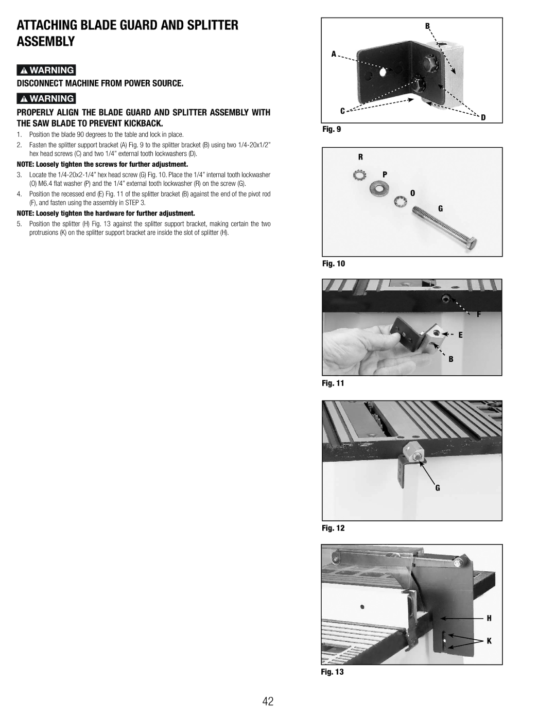
1.Position the blade 90 degrees to the table and lock in place.
2.Fasten the splitter support bracket (A) Fig. 9 to the splitter bracket (B) using two
NOTE: Loosely tighten the screws for further adjustment.
3.Locate the
(O) M6.4 flat washer (P) and the 1/4” external tooth lockwasher (R) on the screw (G).
4.Position the recessed end (E) Fig. 11 of the splitter bracket (B) against the end of the pivot rod (F), and fasten using the assembly in STEP 3.
NOTE: Loosely tighten the hardware for further adjustment.
5.Position the splitter (H) Fig. 13 against the splitter support bracket, making certain the two protrusions (K) on the splitter support bracket are inside the slot of splitter (H).
| B |
A |
|
C | D |
|
Fig. 9
R
P
O
G
Fig. 10
F
E
B
Fig. 11
G
Fig. 12
H
![]() K
K
Fig. 13
42