ENGLISH
FEATURES (FIG. 1, 4)
A. | Lock Chain | I. | Vise Lever |
B. | Spark deflector screw | J. | Wheel |
C. | Spark deflector | K. | Guard |
D. | Base | L. | Spindle Lock |
E. | Fence | M. | Depth Stop Bolt and Jam Nut |
F. | Vise | N. | Trigger Switch |
G. | Flat Wrench | O. | Padlock Hole |
H. | Crank | P. | Fence Bolts |
POWER SUPPLY
Be sure your power supply agrees with the nameplate marking. A voltage decrease of more than 10% will cause a loss of power and overheating.
CUTTING CAPACITY
The wide vise opening and high pivot point provide cutting capacity for many large pieces. Use the cutting capacity chart to determine total maximum size of cuts that can be made with a new wheel.
![]() CAUTION: CERTAIN LARGE, CIRCULAR OR IRREGULARLY SHAPED OBJECTS MAY REQUIRE ADDITIONAL HOLDING MEANS IF THEY CANNOT BE HELD SECURELY IN VISE.
CAUTION: CERTAIN LARGE, CIRCULAR OR IRREGULARLY SHAPED OBJECTS MAY REQUIRE ADDITIONAL HOLDING MEANS IF THEY CANNOT BE HELD SECURELY IN VISE.
![]() CAUTION: DO NOT CUT MAGNESIUM WITH THIS TOOL.
CAUTION: DO NOT CUT MAGNESIUM WITH THIS TOOL.
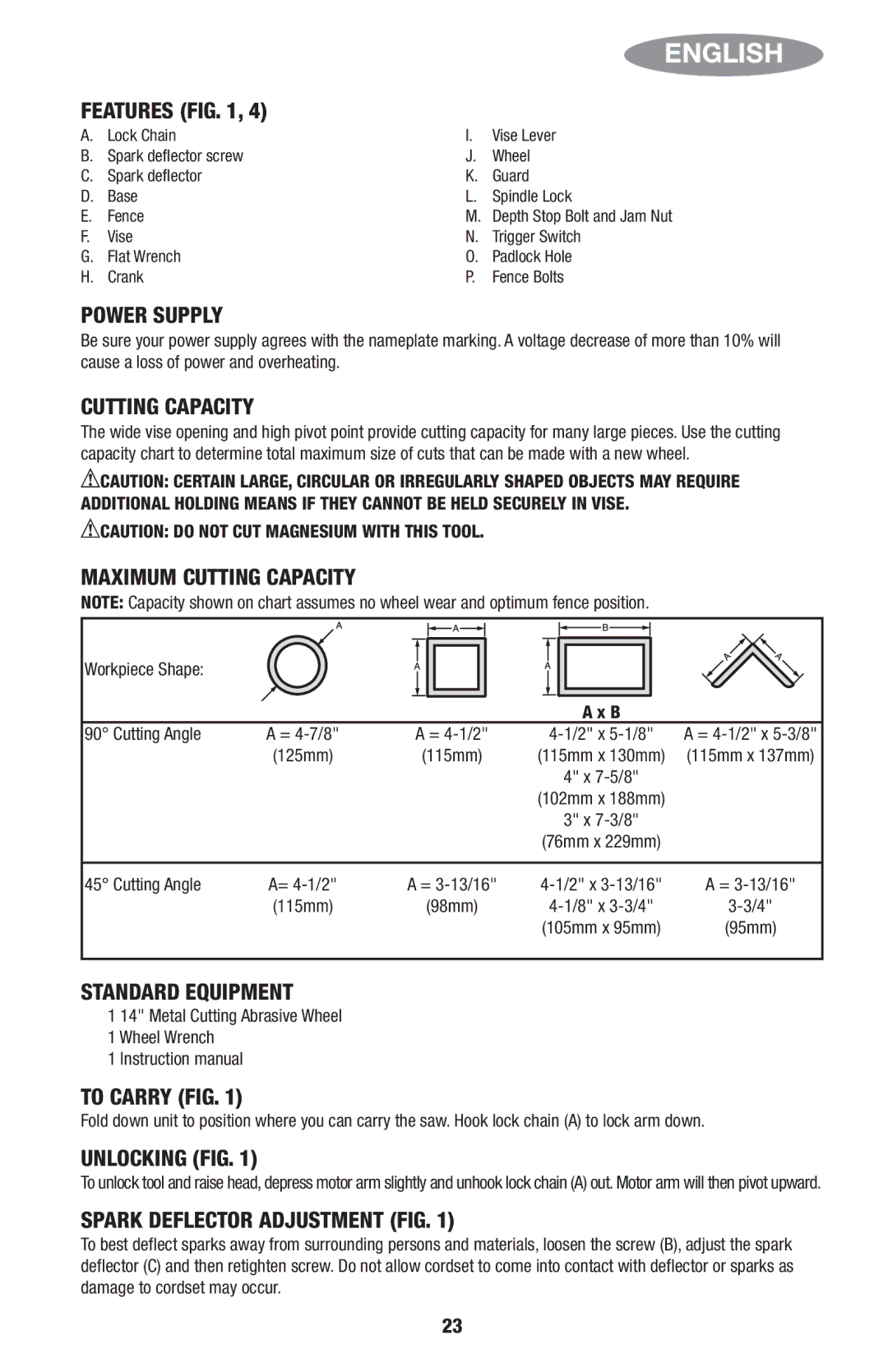
MAXIMUM CUTTING CAPACITY
NOTE: Capacity shown on chart assumes no wheel wear and optimum fence position.
Workpiece Shape:
|
|
| A x B |
|
90° Cutting Angle | A = | A = | A = | |
| (125mm) | (115mm) | (115mm x 130mm) | (115mm x 137mm) |
|
|
| 4" x |
|
|
|
| (102mm x 188mm) |
|
|
|
| 3" x |
|
|
|
| (76mm x 229mm) |
|
|
|
|
|
|
45° Cutting Angle | A= | A = | A = | |
| (115mm) | (98mm) | ||
|
|
| (105mm x 95mm) | (95mm) |
STANDARD EQUIPMENT
1 14" Metal Cutting Abrasive Wheel
1 Wheel Wrench
1 Instruction manual
TO CARRY (FIG. 1)
Fold down unit to position where you can carry the saw. Hook lock chain (A) to lock arm down.
UNLOCKING (FIG. 1)
To unlock tool and raise head, depress motor arm slightlyunhookand lock chain(A) out. Motor arm will then pivot upward.
SPARK DEFLECTOR ADJUSTMENT (FIG. 1)
To best deflect sparks away from surrounding persons and materials, loosen the screw (B), adjust the spark deflector (C) and then retighten screw. Do not allow cordset to come into contact with deflector or sparks as damage to cordset may occur.
23