ATTACHING MITER GAUGE HOLDER
![]() DISCONNECT MACHINE FROM POWER SOURCE.
DISCONNECT MACHINE FROM POWER SOURCE.
E
F![]()
A
B
G
Fig. 5
Fig. 6
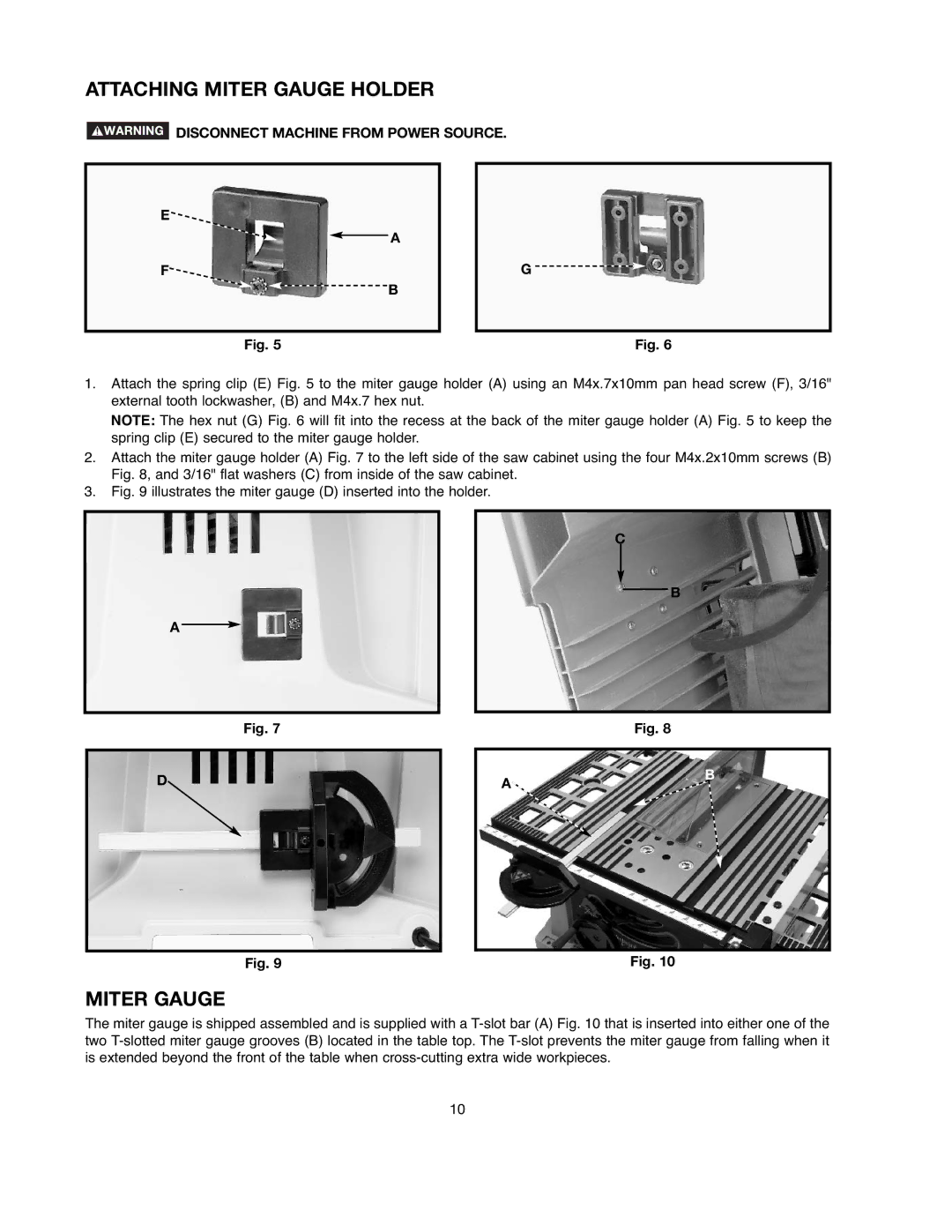
1.Attach the spring clip (E) Fig. 5 to the miter gauge holder (A) using an M4x.7x10mm pan head screw (F), 3/16" external tooth lockwasher, (B) and M4x.7 hex nut.
NOTE: The hex nut (G) Fig. 6 will fit into the recess at the back of the miter gauge holder (A) Fig. 5 to keep the spring clip (E) secured to the miter gauge holder.
2.Attach the miter gauge holder (A) Fig. 7 to the left side of the saw cabinet using the four M4x.2x10mm screws (B) Fig. 8, and 3/16" flat washers (C) from inside of the saw cabinet.
3.Fig. 9 illustrates the miter gauge (D) inserted into the holder.
A
Fig. 7
C
B
Fig. 8
D
A
B
Fig. 9
Fig. 10
MITER GAUGE
The miter gauge is shipped assembled and is supplied with a
10