ENGLISH
dangerous and must be repaired.
c.Disconnect the plug from the power source and/or the battery pack from the power tool before making any adjustments, changing accessories, or storing power tools. Such preventive safety measures reduce the risk of starting the power tool accidentally.
d.Store idle power tools out of the reach of children and do not allow persons unfamiliar with the power tool or these instructions to operate the power tool. Power tools are dangerous in the hands of untrained users.
e.Maintain power tools. Check for misalignment or binding of moving parts, breakage of parts and any other condition that may affect the power tools operation. If damaged, have the power tool repaired before use.Many accidents are caused by poorly maintained power tools.
f.Use the power tool, accessories and tool bits etc., in accordance with these instructions, taking into account the working conditions and the work to be performed. Use of the power tool for operations different from those intended could result in a hazardous situation.
5. Service
a.Have your power tool serviced by a qualified repair person using only identical replacement parts.This will ensure that the safety of the power tool is maintained.
6. Electrical safety
Your tool is double insulated; therefore no earth wire is required.
Always check that the main voltage corresponds to the voltage on the rating plate.
Warning! If the power cord is damaged, it must be replaced by the manufacturer, authorized Black & Decker Service Center or an equally qualified person in order to avoid damage or injury. If the power cord is replaced by an equally qualified person, but not authorized by Black & Decker, the warranty will not be valid.
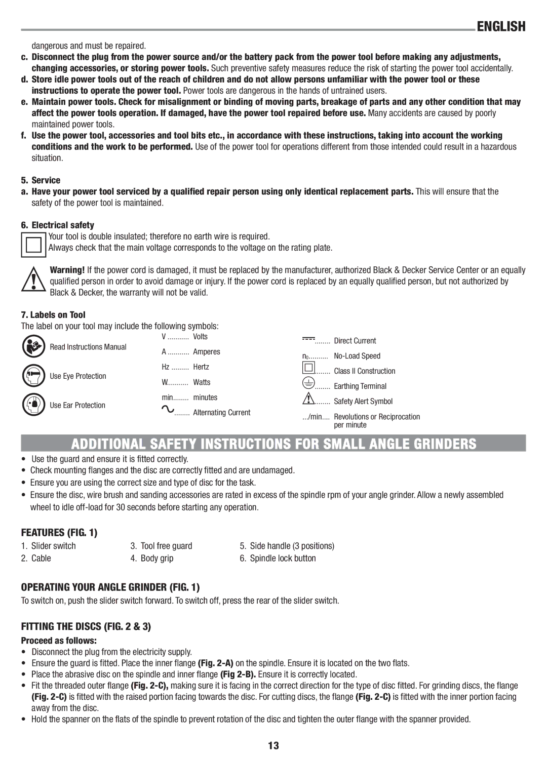
7. Labels on Tool
The label on your tool may include the following symbols:
| V | Volts | |
Read Instructions Manual | A | Amperes | |
| |||
Use Eye Protection | Hz | Hertz | |
W | Watts | ||
| |||
Use Ear Protection | min | minutes | |
| Alternating Current | ||
| ........ |
|
|
|
| Direct Current | |
n0 | |||||
|
|
| ........ | Class II Construction | |
|
|
|
| Earthing Terminal | |
|
|
|
| ||
|
|
|
| ||
|
|
| ........ | ||
|
|
| ........ | Safety Alert Symbol | |
.../min.... | Revolutions or Reciprocation | ||||
|
|
|
| per minute | |
ADDITIONAL SAFETY INSTRUCTIONS FOR SMALL ANGLE GRINDERS
•Use the guard and ensure it is fitted correctly.
•Check mounting flanges and the disc are correctly fitted and are undamaged.
•Ensure you are using the correct size and type of disc for the task.
•Ensure the disc, wire brush and sanding accessories are rated in excess of the spindle rpm of your angle grinder. Allow a newly assembled wheel to idle
FEATURES (FIG. 1)
1. | Slider switch | 3. | Tool free guard | 5. | Side handle (3 positions) |
2. | Cable | 4. | Body grip | 6. | Spindle lock button |
OPERATING YOUR ANGLE GRINDER (FIG. 1)
To switch on, push the slider switch forward. To switch off, press the rear of the slider switch.
FITTING THE DISCS (FIG. 2 & 3)
Proceed as follows:
•Disconnect the plug from the electricity supply.
•Ensure the guard is fitted. Place the inner flange(Fig.
•Place the abrasive disc on the spindle and inner flange(Fig
•Fit the threaded outer flange (Fig.
•Hold the spanner on the flats of the spindle to prevent rotation of the disc and tighten the outer flange with the spanner provided.
13