
PW1600 specifications
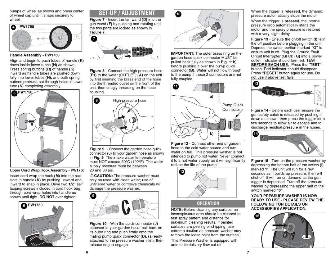
The Black & Decker PW1750, PW1600, and 598667-00 are notable additions to the realm of pressure washers, showcasing a blend of power, efficiency, and advanced features designed to tackle a variety of cleaning tasks. These models are perfect for homeowners and professionals seeking reliable solutions for outdoor cleaning, including decks, patios, vehicles, and driveways.The PW1750 boasts a powerful 1750 PSI (pounds per square inch) and a flow rate of 1.2 GPM (gallons per minute), making it an effective tool for removing tough dirt and grime. It is equipped with a 13-amp electric motor, ensuring consistent performance without the need for gas or oil. Its lightweight and compact design make it easy to maneuver and store, while the built-in carry handle enhances portability.
One of the standout features of the PW1750 is its adjustable spray nozzle, which allows users to customize the pressure according to the cleaning task at hand. This versatility is essential for switching between delicate surfaces like vehicles and sturdy areas such as concrete. The integrated detergent tank simplifies the process of applying soap, enhancing the effectiveness of cleaning.
Similarly, the PW1600, with its 1600 PSI and 1.2 GPM, combines efficacy with user-friendliness. Designed for quick assembly and operation, this model provides a cost-effective solution for lighter duty cleaning tasks. Its compact build does not compromise on power, featuring a robust electric motor that ensures reliable operation.
The 598667-00 is another remarkable device in this lineup, designed with a focus on durability and innovative features. Its sturdy construction ensures longevity, while the ergonomic handle and wheels promote convenience and ease of use. It also incorporates safety features such as a total stop system (TSS) that automatically shuts off the pump when the trigger is released, preventing damage and conserving energy.
All three models represent Black & Decker’s commitment to quality engineering and consumer satisfaction. They come with a variety of accessories, including multiple nozzle tips, a high-pressure hose, and detergent containers, which further enhance their versatility. Easy maintenance, user-friendly operation, and exceptional performance make the PW1750, PW1600, and 598667-00 ideal choices for anyone serious about outdoor cleaning tasks. Whether it's routine cleaning or tackling stubborn stains, these pressure washers provide the power and reliability needed for effective results.