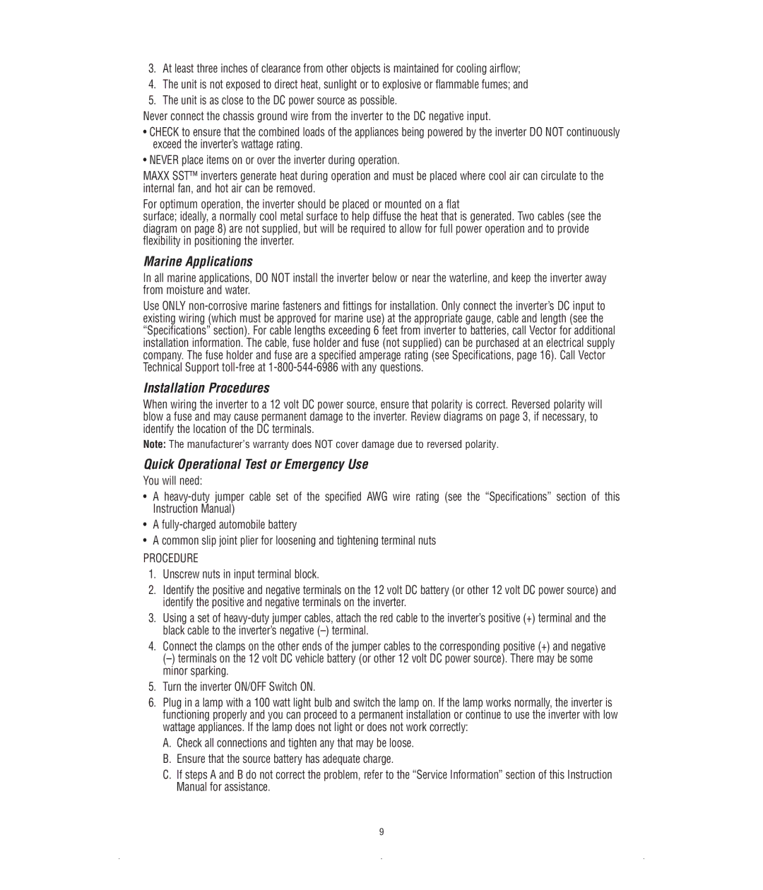
3.At least three inches of clearance from other objects is maintained for cooling airflow;
4.The unit is not exposed to direct heat, sunlight or to explosive or flammable fumes; and
5.The unit is as close to the DC power source as possible.
Never connect the chassis ground wire from the inverter to the DC negative input.
•CHECK to ensure that the combined loads of the appliances being powered by the inverter DO NOT continuously exceed the inverter’s wattage rating.
•NEVER place items on or over the inverter during operation.
MAXX SST™ inverters generate heat during operation and must be placed where cool air can circulate to the internal fan, and hot air can be removed.
For optimum operation, the inverter should be placed or mounted on a flat
surface; ideally, a normally cool metal surface to help diffuse the heat that is generated. Two cables (see the diagram on page 8) are not supplied, but will be required to allow for full power operation and to provide flexibility in positioning the inverter.
Marine Applications
In all marine applications, DO NOT install the inverter below or near the waterline, and keep the inverter away from moisture and water.
Use ONLY
Installation Procedures
When wiring the inverter to a 12 volt DC power source, ensure that polarity is correct. Reversed polarity will blow a fuse and may cause permanent damage to the inverter. Review diagrams on page 3, if necessary, to identify the location of the DC terminals.
Note: The manufacturer’s warranty does NOT cover damage due to reversed polarity.
Quick Operational Test or Emergency Use
You will need:
•A
•A
•A common slip joint plier for loosening and tightening terminal nuts
PROCEDURE
1.Unscrew nuts in input terminal block.
2.Identify the positive and negative terminals on the 12 volt DC battery (or other 12 volt DC power source) and identify the positive and negative terminals on the inverter.
3.Using a set of
4.Connect the clamps on the other ends of the jumper cables to the corresponding positive (+) and negative
5.Turn the inverter ON/OFF Switch ON.
6.Plug in a lamp with a 100 watt light bulb and switch the lamp on. If the lamp works normally, the inverter is functioning properly and you can proceed to a permanent installation or continue to use the inverter with low wattage appliances. If the lamp does not light or does not work correctly:
A. Check all connections and tighten any that may be loose. B. Ensure that the source battery has adequate charge.
C. If steps A and B do not correct the problem, refer to the “Service Information” section of this Instruction Manual for assistance.
9
